Control & Connection Panel
Control & Connection Panel
Ⅱ
. Inside of Tanzanite Model
1.
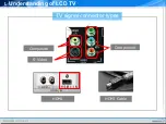
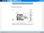
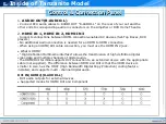
AUDIO OUT(R-AUDIO-L)
- Connect RCA audio cables to AUDIO OUT "R-AUDIO-L" on the rear of your set and the
other ends to corresponding audio in connectors on the Amplifier or DVD Home Theatre.
2.
HDMI IN 1, HDMI IN 2, HDMI IN 3
- Supports connections between HDMI-connection-enabled AV devices (Set-Top Boxes, DVD
players)
- No additional Audio connection is needed for an HDMI to HDMI connection.
-When using an HDMI/DVI cable connection, you must use the HDMI IN 2 jack.
★
What is HDMI?
- “High Definition Multimedia interface” allows the transmission of high definition digital
video data and multiple channels of digital audio.
-The HDMI/DVI terminal supports DVI connection to an extended device with the appropriate
cable (not supplied). The difference between HDMI and DVI is that the HDMI device is
smaller in size, has the HDCP (High Bandwidth Digital Copy Protection) coding feature
installed, and supports multi - channel digital audio.
DVI IN(HDMI2)[R-AUDIO-L]
- DVI audio outputs for external devices.
★
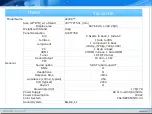
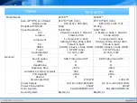
Supported modes for HDMI/DVI and Component
Summary of Contents for LE32A Series
Page 1: ...LCD TV Tanzanite TRAINING MANUAL ...
Page 3: ...Ⅰ Understanding of LCD TV UNDERSTANDING OF LCD TV ...
Page 12: ...Ⅱ Inside of Tanzanite Model Inside of Tanzanite Model ...
Page 17: ...Ⅱ Inside of Tanzanite Model Control Connection Panel Control Connection Panel ...
Page 48: ...DECODER D61211GM Ⅱ Inside of Tanzanite Model ...
Page 55: ...SOUND AMP NTP3100 Package 56 pin MLF 8mm by 8mm Ⅱ Inside of Tanzanite Model ...
Page 56: ...SOUND AMP NTP3100 PIN DESCRIPTIONS Ⅱ Inside of Tanzanite Model ...
Page 57: ...DTV COMP SW BA7657 BLOCK DIAGRAM Ⅱ Inside of Tanzanite Model ...
Page 59: ...BOARD DESCRIPTION Ⅲ Board description ...
Page 61: ...CONTROL SPEAKER JACK MAIN BOARD LAYOUT MAIN BOARD LAYOUT ...
Page 67: ...Ⅲ Board description IP SPEC IP SPEC MAIN BOARD LAYOUT MAIN BOARD LAYOUT ...
Page 68: ...Ⅲ Board description IP SPEC IP SPEC MAIN BOARD LAYOUT MAIN BOARD LAYOUT ...
Page 69: ...Ⅲ Board description IP SPEC IP SPEC MAIN BOARD LAYOUT MAIN BOARD LAYOUT ...
Page 70: ...Ⅲ Board description IP SPEC IP SPEC MAIN BOARD LAYOUT MAIN BOARD LAYOUT ...
Page 71: ...Ⅲ Board description IP SPEC IP SPEC MAIN BOARD LAYOUT MAIN BOARD LAYOUT ...
Page 72: ...Ⅲ Board description IP SPEC IP SPEC MAIN BOARD LAYOUT MAIN BOARD LAYOUT ...
Page 75: ...IV Disassembly DISASSEMBLY ...
Page 76: ...IV Disassembly Disassembly Tanzanite ...
Page 77: ...IV Disassembly ...
Page 78: ...IV Disassembly ...
Page 79: ...IV Disassembly ...
Page 80: ...IV Disassembly ...
Page 81: ...V Trouble Shooting TROUBLE SHOOTING ...
Page 87: ...V Trouble Shooting ...
Page 88: ...V Trouble Shooting R G B Output Signal ...
Page 89: ...V Trouble Shooting Digital Output Data Signal of HDMI Data ...
Page 90: ...V Trouble Shooting CVBS Output Signal Tuner CVBS Output Signal ...
Page 91: ...V Trouble Shooting Digital Output Data Analog Signal Y C ...
Page 92: ...V Trouble Shooting The Signal Inputed to IC2002 The Signal Inputed to IC2001 ...
Page 93: ...V Trouble Shooting ...
Page 94: ...HOW TO UPGRADE ...
Page 101: ...ATTACHMENT ...
Page 102: ...CONTENTS CONTENTS I What is HDMI II What is a TrusurroundXT ...
Page 104: ...HDMI block diagram What is HDMI Attachment ...
Page 106: ...Connector Drawings All dimensions in millimeters What is HDMI Attachment ...
Page 108: ...HDMI Encoder Decoder Overview What is HDMI Attachment ...
Page 110: ...Example TMDS periods in 720x480p video frame What is HDMI Attachment ...


