14 Reference Infomation
14-3
14-2 Connecting the Monitor
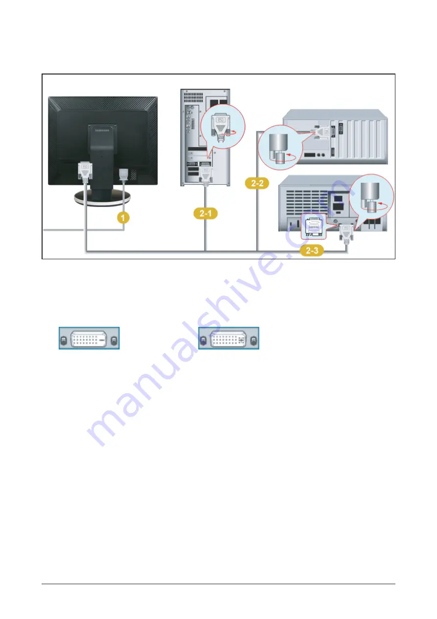
1. Connect the power cord for your monitor to the power port on the back of the monitor.
Plug the power cord for the monitor into a nearby outlet.
2-1. Using the DVI (Digital) connector on the video card.
- Connect the DVI Cable to the DVI Port on the back of your Monitor.
2-2. Connected to a Macintosh.
-Connect the monitor to the Macintosh computer using the DVI connection cable.
2-3. In the case of an old model Macintosh, you need to connect the monitor using a special Mac adapter.
3. Turn on your computer and monitor. If your monitor displays an image, installation is complete.
●
Rear of Monitor
●
Rear of Computer
●
New Model Macintosh
●
Old Model Macintosh
DVI-D
DVI-I
Summary of Contents for Lacie720
Page 8: ...1 Precautions 1 4 Memo ...
Page 16: ...Memo 2 Product Specifications 2 8 ...
Page 22: ...3 Alignments and Adjustments 3 6 Memo ...
Page 25: ...4 Troubleshooting 4 3 WAVEFORMS Figure 1 PC Analog signal Waveforms ...
Page 27: ...4 Troubleshooting 4 5 WAVEFORMS Figure 2 PC Digital Signal Waveforms ...
Page 28: ...4 Troubleshooting 4 6 4 4 Main Circuit and Each Part Number Figure 3 Main Circuit ...
Page 50: ...7 Block Diagrams 7 2 7 2 Power Board Figure 2 Power Board Block Diagram ...
Page 51: ...8 Wiring Diagram 8 1 8 Wiring Diagram ...
Page 52: ...8 Wiring Diagram 8 2 Memo ...
Page 54: ...9 Schematic Diagrams 9 2 This Document can not be used without Samsung s authorization ...
Page 55: ...9 Schematic Diagrams 9 3 This Document can not be used without Samsung s authorization ...
Page 56: ...9 Schematic Diagrams 9 4 This Document can not be used without Samsung s authorization ...
Page 57: ...9 Schematic Diagrams 9 5 This Document can not be used without Samsung s authorization ...
Page 58: ...Memo 9 Schematic Diagrams 9 6 ...
Page 64: ...10 Operating Instructions and Installation 10 6 Memo ...
Page 69: ...12 PCB Daigram 12 1 12 PCB Diagram 12 1 Main Board Part Description ...
Page 70: ...12 PCB Diagram 12 2 12 2 Main Board Part Number ...


