3 Alignments and Adjustments
3-1
3-1 Required Equipment
The following equipment is necessary for adjusting the monitor:
Computer with Windows 95, Windows 98, Windows NT, Windows 2000, or Windows XP.
MTI-2050/MTI-2055 DDC MANAGER JIG
3-2 Automatic Color Adjustment
To input video, use 16 gray or any pattern using black and white.
1. Press and hold down both the Source Key and
key at the same time for about 5 seconds.
2. A blinking display informs you that the automatic color adjustment process is completed.
3. The automatic color adjustment feature is also available in the service function.
3-3 DDC EDID Data Input
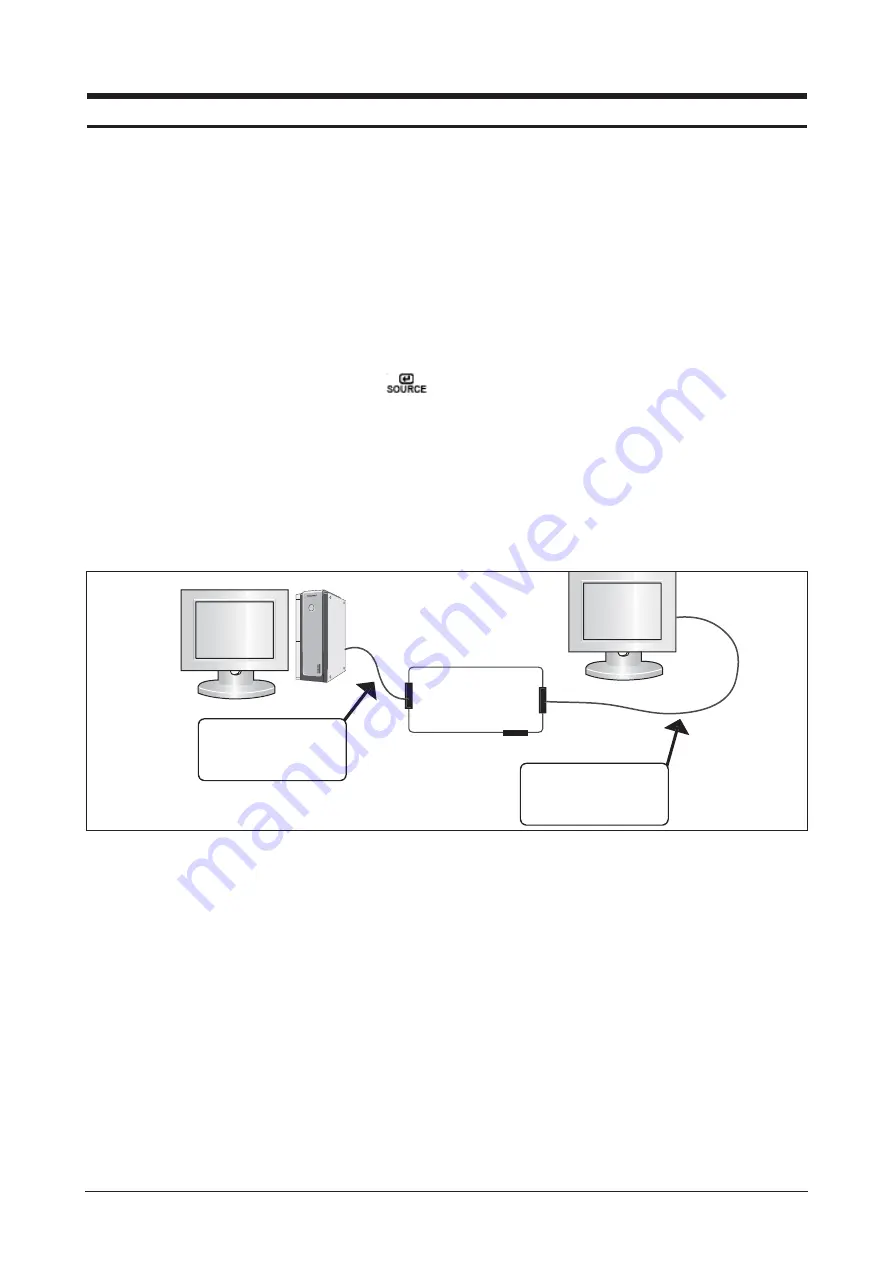
1. After exchange the Main Board, We use the DDC control JIG and must complete downloading.
Connecting is refer to below picture.
2. Receive/Download the proper DDC file for the model from HQ(SAMSUNG in Suwon) quality control department.
Install the below jig(Figure 1) and enter the data.
3-4 OSD Adjustment When Replacing Panel
1. Set the Brightness and Contrast to zero,
and push the MENU button more than 5 seconds.
The Function OSD is displayed like Figure 2.
3 Alignments and Adjustments
This section of the service manual explains how to use the Parallel(DDC Manager Tool) JIG. This function is needed
for AD board change and program memory (IC306) change.
Figure 1.
Parallel Connector
(25P Cable)
MTI-2050
MTI-2055
DDC Manager
Connect Monitor
(Signal Cable)
Summary of Contents for Lacie720
Page 8: ...1 Precautions 1 4 Memo ...
Page 16: ...Memo 2 Product Specifications 2 8 ...
Page 22: ...3 Alignments and Adjustments 3 6 Memo ...
Page 25: ...4 Troubleshooting 4 3 WAVEFORMS Figure 1 PC Analog signal Waveforms ...
Page 27: ...4 Troubleshooting 4 5 WAVEFORMS Figure 2 PC Digital Signal Waveforms ...
Page 28: ...4 Troubleshooting 4 6 4 4 Main Circuit and Each Part Number Figure 3 Main Circuit ...
Page 50: ...7 Block Diagrams 7 2 7 2 Power Board Figure 2 Power Board Block Diagram ...
Page 51: ...8 Wiring Diagram 8 1 8 Wiring Diagram ...
Page 52: ...8 Wiring Diagram 8 2 Memo ...
Page 54: ...9 Schematic Diagrams 9 2 This Document can not be used without Samsung s authorization ...
Page 55: ...9 Schematic Diagrams 9 3 This Document can not be used without Samsung s authorization ...
Page 56: ...9 Schematic Diagrams 9 4 This Document can not be used without Samsung s authorization ...
Page 57: ...9 Schematic Diagrams 9 5 This Document can not be used without Samsung s authorization ...
Page 58: ...Memo 9 Schematic Diagrams 9 6 ...
Page 64: ...10 Operating Instructions and Installation 10 6 Memo ...
Page 69: ...12 PCB Daigram 12 1 12 PCB Diagram 12 1 Main Board Part Description ...
Page 70: ...12 PCB Diagram 12 2 12 2 Main Board Part Number ...


