background image

Samsung Electronics

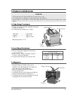
5-4 High Voltage Capacitor

5-5 High Voltage Diode

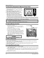
5-6 Main Relay and Power Control Relay

5-7 Adjustment of Primary Switch, Door Sensing Switch and Monitor Switch

5-2

1. Check continuity of the capacitor with the meter set at the highest resistance scale.
2. Once the capacitor is charged, a normal capacitor shows continuity for a short time, and then indicates 9M

Ω.

3. A shorted capacitor will show continuous continuity.
4. An open capacitor will show constant 9M

Ω.

5. Resistance between each terminal and chassis should read infinite.

1. Isolate the diode from the circuit by disconnecting its leads.
2. With the ohm-meter set at the highest resistance scale, measure across the diode terminals. Reverse the

meter leads and read the resistance. A meter with 6V, 9V or higher voltage batteries should be used to
check the front-to back resistance of the diode (otherwise an infinite resistance may be read in both
directions). The resistance of a normal diode will be infinite in one direction and several hundred K

in

the other direction.

1. When mounting Primary switch and Interlock

Monitor switch to Latch Body, consult the figure.

NOTE

: No specific adjustment during   installation

of Primary switch and Monitor switch to the latch
body is necessary.

2. When mounting the Latch Body to the oven

assembly, adjust the Latch Body by moving it so that
the oven door will not have any play in it. Check for
play in the door by pulling the door assembly. Make
sure that the latch keys move smoothly after
adjustment is completed. Completely tighten the
screws holding the Latch Body to  the oven assembly.

3. Reconnect to Monitor switch and check the

continuity of the monitor circuit and all latch
switches again by following the components test
procedures.

4. Confirm that the gap between the switch housing

and the switch actuator is no more than 0.5mm when
door is closed.

1. The relays are located on the PCB Ass'y.  Isolate them from the main circuit by disconnecting the leads. 
2. Operate the microwave oven with a water load in the oven. Set the power level set to high.
3. Check continuity between terminals of the relays after the start pad is pressed.

Precaution

For continued protection against radiation hazard, replace parts in accordance with the wiring diagram and be sure to use the
correct part number for the following switches: Primary and door sensing switches, and the interlock monitor switch (replace all
together). Then follow the adjustment procedures below. After repair and adjustment, be sure to check the continuity of all
interlock switches and the interlock monitor switch.

Alignment and Adjustments

Door Open

Door Closed

Primary switch

0

Monitor switch (COM-NC)

0

Monitor switch (COM-NO)

0

Door Sensing S/W

0

Interlock Monitor S/W

Lever Slider A

Primary Interlock S/W

Door Sensing S/W

Lever Slider B

(Door Close Condition)                                    (Door Open Condition)

Summary of Contents for CE124CF

Page 1: ...ams UHR LEISTUNG GRILL ZEIT GEWICHT AUFTAUEN GAR AUTOMATIK PLUS HEISSLUFT MIKROWELLE MW HEISSL MW GRILL GRILL HEISSL LÖSCHEN START CE124CF SCHNELLGERICHTE 1 GETRÄNKE 2 FOLIENKARTOFFEL 3 PIZZA 4 POMMES FRITES 5 HAMBURGER FISCHSTÄBCHEN 6 REIS NUDELN 7 POPCORN AUFWARMEN 8 FERTIGGERICHTE 9 QUICHE AUFLAUF 10 EINTOPF 11 SUPPE SAUCE 12 REIS NUDELN GAR AUTOMATIK 13 RIND 14 SCHWEIN 15 GEFLÜGEL 16 GEFLÜGELS...

Page 2: ...nicians should remove their watches while repairing an MWO 11 To avoid any possible radiation hazard replace parts in accordance with the wiring diagram Also use only the exact replacements for the following parts Primary and secondary interlock switches interlock monitor switch 12 If the fuse is blown by the Interlock Monitor Switch Replace all of the following at the same time Primary door sensi...

Page 3: ...Short the negative terminal of the high voltage capacitor to the oven chassis Use a screwdriver 3 High voltage is maintained within specified limits by close tolerance safety related components and adjustments If the high voltage exceeds the specified limits check each of the special components 1 2 Pretaution Samsung Electronics 1 2 Special Servicing Precautions Continued 1 3 Special High Voltage ...

Page 4: ...99 MINUTES POWER SOURCE 230V 50Hz AC POWER CONSUMPTION MAX 3 000W MICROWAVE 1 600W GRILL 1 300W CONVECTION 1 400W OUTPUT POWER 90W 900W 10 LEVEL POWER IEC 705 TEST PROCEDURE OPERATING FREQUENCY 2 450MHz MAGNETRON OM75P 10 COOLING METHOD COOLING FAN MOTOR OUTSIDE DIMENSIONS 558 W x 381 H x 496 D ...

Page 5: ...UTTONS Clock set Microwave Power Level select Defrost Auto cook and Dish select More Less Min Plus Min Minus Convection grill Combination cook Timer Weight set Stop Cancel Start 3 Operating Instructions 3 1 Control Panel 3 2 Features Accessories ROLLER RING CONTROL PANEL HEATER GRILL BARBECUE BAR HOLDER OVEN LAMP GLASS TRAY OVEN DOOR THERMIISTOR SENSOR WINDOW DISPLAY OPEN DOOR UHR LEISTUNG GRILL Z...

Page 6: ...nd damper assembly 2 Remove four screws 1 securing damper Ass y 3 Remove two screws 2 securing magnetron thermostat 4 Remove four magnetron flange nuts at top 1 When removing the magnetron make sure that its antenna does not hit any adjacent parts or it may be damaged 2 when replacing the magnetron be sure to remount the magnetron gasket in the correct position and make sure the gasket is in good ...

Page 7: ...y is not mounted properly microwave may leak from the clearance between the door and oven 3 Perform the microwave leakage test 4 5 Replacement of H V Transformer 1 Discharge the high voltage capacitor 2 Disconnect all the leads from the high voltage transformer 3 Remove the mounting bolts on the high voltage transformer 4 When replacing connect the leads correctly and firmly Disconnect the oven fr...

Page 8: ...late 4 Disconnect all the lead wires from the drive motor 5 Remove screws 1 securing the drive motor to the cavity 6 Take out the drive motor 7 When replacing the drive motor be sure to remount it in the correct position 1 D RIN KS 2 JAC KETPO TATO 3 P IZZ A 4 O VENCH IPS 5 B UR GE RS FIS HFIN GE RS 6 R ICE PA STA 7 P OP CO RN AU TO RE HE AT 8 P LAT ED ME AL 9 P IE Q UIC HE 10 CA SSER OLE 11 SO UP...

Page 9: ...ricity from your body and avoid touching the Touch control clrcuitry 2 Disconnect the connectors from the control circuit board 3 Remove screws securing the control circuit bord 4 Lift up the control circuit board from right side and remove the hooks holding the contol circuit board to the box assembly Disassembly and Reassembly Screws Screws ...

Page 10: ...e one ohm or less 3 A continuity check between each filament terminal and magnetron case should read open 1 The low voltage transformer is located on the control circuit board 2 Remove the low voltage transformer from the PCB Ass y and check continuity 3 Normal resistor reading is shown in the table PRECAUTION 1 High voltage is present at the high voltage terminals during any cook cycle 2 It is ne...

Page 11: ...h Body by moving it so that the oven door will not have any play in it Check for play in the door by pulling the door assembly Make sure that the latch keys move smoothly after adjustment is completed Completely tighten the screws holding the Latch Body to the oven assembly 3 Reconnect to Monitor switch and check the continuity of the monitor circuit and all latch switches again by following the c...

Page 12: ...r glass vessel with water 2 Stir water in glass vessel with thermometer and record glass vessel s temperature T1 10 1 C 3 After moving the water into another glass vessel place it in the center of the cooking tray Set the oven to high power and operate for 48seconds exactly 1 5 seconds included as a holding time of magnetron oscillation 4 When heating is finished stir the water again with the ther...

Page 13: ...edure for Measurement of Microwave Energy Leakage 5 12 Note on Measurement 5 11 Check for Microwave Leakage 5 13 1 Record keeping and notification after measurement 1 After adjustment and repair of a radiarion preventing device make a repair record for the measured values and keep the data 2 If the radiation leakage is more than 4 mW cm2 after determining that all parts are in good condition funct...

Page 14: ...sing switch 3 Defective monitor switch NOTE1 4 Shorted HVCapacitor 5 Shorted HVTransformer NOTE2 NOTE 1 All of these switches must be replaced at the same time refer to adjustment instructions Check continuity of power relay contacts and if it has continuity replace power relay also NOTE 2 When HVTransformer is replaced check diode and magnetron also Oven does not accept 1 Key input is not in Sequ...

Page 15: ...d 1 Loose fan and fan motor Tighten screws of fan motor 2 Loose screws on H V Transformer Tighten screws of H V Transformer 3 Shorted H V Diode Replace H V Diode Turntable motor does not rotate 1 Open or loose wiring of turntable motor Check the wire of turntable motor 2 Defective turntable motor Replace turntable motor Oven stops operation during cooking 1 Open or loose wiring of primary Adjust d...

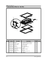
Page 16: ...ed Views 7 1 76 75 48 61 62 46 64 65 66 67 73 6 74 4 2 7 1 10 5 3 77 42 72 78 55 63 51 52 82 47 69 68 53 54 49 50 59 56 60 43 8 9 57 38 40 44 45 36 41 39 37 33 34 30 29 28 32 31 35 22 25 26 27 23 86 20 17 15 19 14 21 18 13 16 12 70 87 88 83 84 85 58 24 71 79 80 81 ...

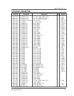
Page 17: ...UPLER BARBECUE AL 1 30 DE31 10057A MOTOR SYNCHRONOUS MULJ24ZR03 SPIT MOTOR 1 31 DE72 40034A DAMPER SILICON SILICONE 1 32 DE72 40037A DAMPER PLATE SECC T0 6 1 33 DE62 90015B ADIABATIC R EGF E3019 PBS T15 W346 L282 AL 1 35 DE71 60216A COVER DAMPER NYLON 66 2411GF 143 7G 1 34 DE71 60230D COVER ADIABATIC R SBHG1 M T0 5 1 35 DE71 60216A COVER DAMPER NYLON 66 2411GF 143 7G 1 36 DE66 40027A BODY LATCH NU...

Page 18: ... 20044A THERMOSTAT PW 2N 150 60 BKT23 8MM 1 GRILL 74 DE92 90100B ASSY GUIDE AIR RE 1280 1270 1 75 DE92 90072A ASSY BASE ROLLER RE 909CG 1 76 DE74 20045A TRAY CERAMIC RE 909CG 1 77 DE93 90038A ASSY B RESISTOR FX175Z D 1 78 DE61 50238A BRACKET PLATE SECC T0 6 1 79 DE64 20045A HANDLE BARBECUE TEMPERED SPRAY BLK 2 80 DE74 20107A TRAY BROILER AL T0 8 345 345 PI345 ENAMEL S 1 81 DE92 90009A ASSY SPIT RA...

Page 19: ...9E SCREEN DOOR B TEMP GLASS T3 2XW313XL435 VITA 1 3 DE92 50037A ASSY DOOR E SILICON BONDING 1 4 DE64 40103A DOOR C PBT 1500G 158G 1 5 DE64 40124A DOOR KEY NYLON 66 2411GF 5 1G 2 6 DE92 90138A ASSY BRACKET SLIDER RE 909CG 1 7 DE61 70057B SPRING KEY HSWR PI1 2 D5 8 L47 1 8 DE92 90052A ASSY HINGE U SBC1 T2 0 1 9 DE73 90018A FERRITE DB 867CPE T4 1 W7 0 L1310 1 10 DE60 60021A PIN DOOR MSWR ZPC3 2 1 2 3...

Page 20: ...WH 01 K 16G 1 6 DE66 20042A BUTTON SELECT R PC LEXAN 141 RP WH 01 K 10G 1 7 DE66 20080A BUTTON CLOCK PC LEXAN 141 RP WH 01 K 1G RE 1 8 DE66 20024A BUTTON MORE PC LEXAN 141 RP WH 01 K 7G RE 1 9 DE61 50072A BRACKET PANEL SECC T0 8 W107 L286 35 1 12 DE39 30091A WIRE LEAD PCB B L60 RE 1280 SAW AMFO 1 13 DE64 10038C KNOB VOLUME PC LEXAN 141 WHT 5G CIRCLE PR 1 14 DE61 70076A SPRING BUTTON HSWR PI0 6 2 1...

Page 21: ... COVER RE 1280 NEW SYSTEM VI 1 5 DE61 50192A BRACKET HEATER B STS430 T0 8 W28 5 L65 4 RE 128 2 6 DE60 30016B NUT FLANGE M4 MSWR10 FEFN 3 BL FAN HEATER 7 DE31 90019A BLADE FAN SECC T0 6 1 8 DE91 50031A ASSY CONV MOTOR AMM90 004AUEA 230V0 33A 1 9 DE47 20044A THERMOSTAT PW 2N 150 60 BKT23 8MM 1 10 DE60 40026A WASHER PLAIN ID5 5 OD12 T1 0 SBC1 1 11 DE62 10014A INSULATION TCO T2 0 W34 L26 YEL 1 12 DE92...

Page 22: ...0 FRFZY 4 DAMPER DE60 10080A SCREW WASHER M5 L12 2S 4 HVT DE60 10082H SCREW A 2S 4X12 TOOTHED 1 A B RE DE60 10082H SCREW A 2S 4X12 TOOTHED 1 A REST DE60 10082H SCREW A 2S 4X12 TOOTHED 2 B PLTE DE60 10082H SCREW A 2S 4X12 TOOTHED 1 B HVC DE60 10082H SCREW A 2S 4X12 TOOTHED 2 B U HI DE60 10082H SCREW A 2S 4X12 TOOTHED 11 BACK P DE60 10082H SCREW A 2S 4X12 TOOTHED 2 BD LAT DE60 10082H SCREW A 2S 4X12...

Page 23: ...815 5V C15 1uF 5V ENCODER SWITCH R25 1K J R26 1K J R27 10K J R28 10K J DOOR S W CON03 THERMISTOR C12 0 1uF R23 2K J R38 1M J R37 1M J R24 1K F R22 5K F Q12 A539 R21 10K J R18 3 9K J R17 3 9K J R19 100K F R20 3 9K J INRUSH RELAY GRILL RELAY FAN RELAY DAMPER RELAY CONV M RELAY CONV H RELAY 33 53 54 55 56 57 58 59 60 TIME COOK COMBI 2 M C MIN MIN START OPTION OPTION 20V G1 G2 G3 G4 p o n m l k j i h ...

Page 24: ...01 R02 R03 P25 2001 000065 R CARBON 10KOHM 5 1 4W AA TP 2 4X6 4MM 5 R06 R07 R08 R12 R14 P25 2001 000065 R CARBON 10KOHM 5 1 4W AA TP 2 4X6 4MM 2 R16 R21 P26 2001 000076 R CARBON 47KOHM 5 1 4W AA TP 2 4X6 4MM 4 R33 R34 R35 R36 P27 2001 000432 R CARBON 1MOHM 5 1 4W AA TP 2 4X6 4MM 2 R24 R25 P28 2001 000575 R CARBON 2KOHM 5 1 4W AA TP 2 4X6 4MM 2 R10 R23 P29 2001 000611 R CARBON 3 9KOHM 5 1 4W AA TP ...

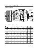
Page 25: ... ORG WHT H V TRANS H V FUSE 0 8A RED RED H V C 1 13uF H V D F MAGNETRON CONDITION OF OVEN DOOR OPENED PLUG IN CONNECTOR A CONNECTOR C PRIMARY SWITCH DAMPER RY GRY BLU NC NC COM NO WHT DAMPER SWITCH NO 0 15uF CAP Y G 1 3mH FUSE 15A NOISE FILTER C3 2200pF C1 0 1uF 500K OHM C2 2200pF BLK MGT T C O S W SEC S W RY F RED Samsung Electronics Condition DOOR DOOR MICRO GRILL CONVEC MWO MWO GRILL ITEM OPEN ...

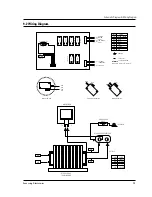
Page 26: ... SYMBOL COLOR Y G YELLOW GREEN BLK BLACK WHT WHITE BLU BLUE BRN BROWN GRY GRAY YEL YELLOW ORG ORANGE RED RED GROUND PARTS LINE PCB PATTERN LINE BLU RED W H A BLU W H B RED ORG RED RED BLU PRIMARY SWITCH DOOR SENSING SWITCH MONITOR SWITCH ORG ORG ORG BRN RED RED RED WHT RED FA F HIGH VOLTAGE TRANSFORMER H V FUSE HIGH VOLTAGE CAPACITOR HIGH VOLTAGE DIODE TO CHASSIS MAGNETRON SYMBOL COLOR ORG ORANGE ...

Reviews: