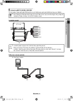
Electric wiring
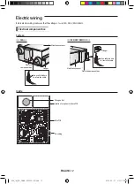
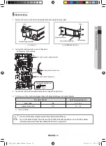
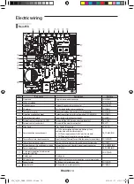
Main PCB
⑥
⑦ ⑧ ⑨ ⑩
⑪
⑱
⑫
⑬
⑭
⑮
①
②
⑯
⑰
⑲
⑳
③
④
⑤
No.
Part name
description
Part No.
①
Download
Program downloader connector
Cn301(BlK)
②
EEPROM SUB PBa
-
Cn201(WHT)
③
Humidity sensor
Outdoor humidity sensor connector
Cn31(WHT)
④
CO
2
sensor
CO
2
(Carbon dioxide) sensor connector
Cn43(BlK)
⑤
Temperature sensor
Indoor and outdoor temperature sensor connector
Cn41(WHT)
⑥
Operation monitoring output
Outputs operation status (Error/Operation On) (MIM-B14)
Cn81(RED)
⑦
Internal damper switch
Inputs damper switch contact signal
Cn52(RED)
⑧
External contact control part (HOOD)
Turn on/off the HOOD mode via external contact
TB_HOOD
⑨
External contact control part
Turn on/off the via external contact
TB_EXT1
⑩
Virus Doctor
Virus Doctor kit connector
Cn801(YEl)
⑪
Communication connection part
F1, F2(Communication between ventilation systems,
communicate with interface module)
V1, V2(Power supply connector for interface module)
F3, F4(Wired remote controller communication)
TB_COMM(BlK)
⑫
Thermal Fuse status input connector
Inputs status of Thermal Fuse within the power terminal block
Cn140(WHT)
⑬
Internal damper power supply
Damper motor control part for switching ventilation mode
Cn72(RED)
⑭
External damper / Humidity power supply
External damper and Humidity power supply connector
TB_DaMPER(BlK)
⑮
Power supply input
220 V/ 60 Hz
TB_POWER(BlK)
⑯
2 wire communication (wired remote
controller) SUB PBa
-
Cn311(WHT)
⑰
Display part
Display part
-
⑱
KEY input part
KEY input part to execute trial operation, reset or view mode
-
⑲
Exhaust motor
Ea (Exhaust air) motor connector
Cn73(WHT)
⑳
Supply motor
Sa (Supplied air) motor connector
Cn74(BlU)
ENGLISH-14
ERV_IM_EN_DB68-05252A-02.indd 14
2016-05-27 오전 11:26:42

