10. Installation
Power wiring diagram
3 phase 3wires 208-230V [AM****XV*F*] 3 phase
3wires 460V [AM****XV*J*]
MCCB+
ELB
MCCB+
ELB
MCCB+
ELB
MCCB+
ELB
ELCB
ELCB
ELCB
ELCB
Main unit
Sub unit
Main unit
Sub unit 1
Sub unit 2
Single phase 2
wires 208-230V
Grounding Grounding Grounding
Wired remote
controller
Wired remote
controller
Communication
ʀɇɵ̷ʪ࣑ĮЇϩʒͱͱθЇ̈͝ϩड़
Outdoor unit)
Communication
ʀɇɵ̷ʪ࣑ĮЇϩʒͱͱθЇ̈͝ϩड़
Indoor unit)
Wired remote
controller
or
or
or
or
Communication cable
࣑ĮЇϩʒͱͱθЇ̈͝ϩड़Ã͝ʒͱͱθ
unit)
Communication cable
࣑ĮЇϩʒͱͱθЇ̈͝ϩड़ĮЇϩʒͱͱθ
unit)
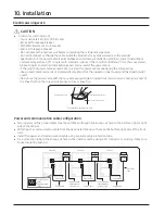
•
Connect a power
cable of the outdoor unit after checking that R-S-T (3 phase 3 wire) is properly connected.
•
Malfunction may occur if one or more of the wires among R-S-T phases (3 Phases - 3 Wires) are not connected
properly.
(*Malfunction : Turing on/off, occurrence of error, consecutive reset)
•
Communication cable between indoor and outdoor units and communication cable between outdoor units has
no polarity.
•
Arrange the cables with a cable tie.
※ ELCB and ELB must be installed since there is risk of electric shock or fire when they are not installed.


