1
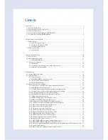
Contents
1. Precautions ..................................................................................................................................................................................................................................... 1
1-1 Precautions for the Service ............................................................................................................................................................................................ 1
1-2 Precautions for the Static Electricity and PL .......................................................................................................................................................... 1
1-3 Precautions for the Safety .............................................................................................................................................................................................. 1
1-4. Precautions for Handling Refrigerant of the DVM CHILLER ......................................................................................................................... 2
1-5. Precautions for Welding the DVM CHILLER Pipe .............................................................................................................................................. 2
2. Product Features and Specifications .................................................................................................................................................................................. 3
2-1. Product Features .............................................................................................................................................................................................................. 3
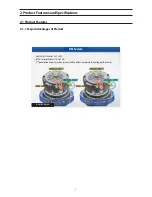
2-1-1. Major Advantages of Product .................................................................................................................................................................... 3
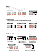
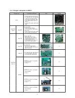
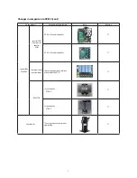
2-1-2. Changes in comparison to DVM S............................................................................................................................................................ 6
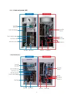
2-1-3. Structure of product (H/P) ............................................................................................................................................................................ 8
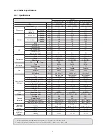
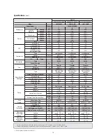
2-2. Product Specifications ................................................................................................................................................................................................... 9
2-2-1.
Specifications...................................................................................................................................................................................................... 9
3. Disassembly and Reassembly ................................................................................................................................................................................................ 10
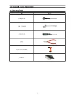
3-1. Necessary Tools ................................................................................................................................................................................................................. 10
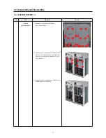
3-2. Disassembly and Reassembly ..................................................................................................................................................................................... 11
3-2-1.
AG042/056/070KSV
666
............................................................................................................................................................................. 11
3-2. Service work of main parts .......................................................................................................................................................................................... 16
3-3-1. Water Pump ........................................................................................................................................................................................................ 16
3-3-2. Temperature sensor & Pressure sensor in the water pipe side .................................................................................................. 18
3-3-3. Plate type heat exchanger PHE ................................................................................................................................................................. 20
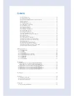
4. Troubleshooting ........................................................................................................................................................................................................................... 29
4-1. Check-up Window Description .................................................................................................................................................................................. 29
4-2. Service Operation ............................................................................................................................................................................................................. 30
4-2-1. Special operation .............................................................................................................................................................................................. 30
4-2-2. DVM Chiller EEPROM code table by models ....................................................................................................................................... 33
4-2-3. Option code by model classification ...................................................................................................................................................... 33
4-2-4. Number Display Method .............................................................................................................................................................................. 34
4-3. Appropriate measures for symptoms..................................................................................................................................................................... 38
4-3-1. Reversed phase / No phase check (Outdoor unit with 3 phase power) ............................................................................... 38
4-3-2. Main PCB has no power phenomenon ................................................................................................................................................. 40
4-3-3. Communication error between hydro and outdoor unit during tracking .......................................................................... 41
4-3-4. Communication error between indoor and outdoor unit after tracking ............................................................................. 43
4-3-5. Internal communication error of the outdoor unit C-Box ............................................................................................................ 44
4-3-6. Internal PCB communication error of the outdoor unit C-Box .................................................................................................. 45
4-3-7. Outdoor temperature sensor error .......................................................................................................................................................... 47
4-3-8. COND OUT temperature sensor error (Open / Short) .................................................................................................................... 48
4-3-9. Outdoor unit COND OUT sensor breakaway error .......................................................................................................................... 49
4-3-10. Compressor discharge or TOP 1/2 temperature sensor error ................................................................................................. 50
4-3-11. Compressor discharge or TOP temperature sensor breakaway error ................................................................................. 51
4-3-12. E269 : Suction temperature sensor breakaway error ................................................................................................................... 52
4-3-13. High pressure sensor error (Open / Short) ........................................................................................................................................ 53
4-3-14. Low pressure sensor error (Open / Short) .......................................................................................................................................... 54
4-3-15. Suction temperature sensor error (Open / Short) .......................................................................................................................... 55
4-3-16. Liquid pipe temperature sensor error (Open / Short) .................................................................................................................. 56
4-3-17. EVI IN temperature sensor error (Open / Short) .............................................................................................................................. 57
4-3-18. EVI OUT temperature sensor error (Open / Short) ......................................................................................................................... 58
4-3-19. Suction-2 temperature sensor error (Open / Short) ..................................................................................................................... 59
4-3-20. Measures of other outdoor unit error .................................................................................................................................................. 60
4-3-21. E407 : COMP DOWN due to high pressure protection control ............................................................................................... 61
4-3-22. E410 : COMP DOWN due to low pressure protection control ................................................................................................. 62
4-3-23. E416: Suspension of starting due to compressor discharge temperature sensor / TOP temperature sensor 63
4-3-24. 3-phase Input Wiring error ........................................................................................................................................................................ 64
4-3-25. E428: : Suspension of starting by abnormal compression ratio .............................................................................................. 65
Summary of Contents for AG042KSVANH
Page 111: ...107 5 6 ASSY PCB MAIN HUB Model All models name is commonness DC 1 2 3 4 5 6 7 8 9 10 11 12 ...
Page 113: ...109 ASSY PCB MAIN HUB cont Model All models name is commonness AC 1 1 2 3 4 5 6 7 8 9 10 11 ...
Page 115: ...111 5 7 ASSY PCB INVERTER PF 8 Model AG042 056KSV666 Series 4 2 3 5 1 8 9 7 6 ...
Page 117: ...113 ASSY PCB INVERTER PF 9 cont Model AG070KSV666 Series 10 8 4 9 7 6 11 12 13 1 2 3 5 ...

