

EB 8384-6S EN
55
Mounting and start-up
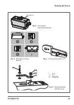
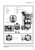
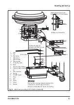
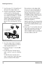
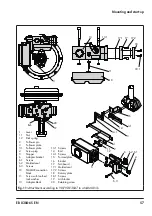
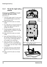
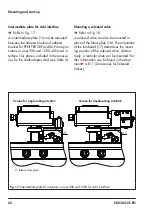
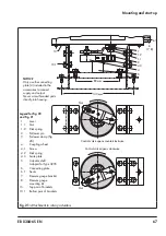
Attachment to NAMUR rib (see Fig. 11)
−
Required mounting parts and accesso
-
ries: see Table 5
−
Observe the travel table on page 28.
1.
Series 240 Valves, actuator size up to
1400-60 cm²:
Screw the two bolts (14)
to the bracket of the stem connector or
directly to the stem connector (depending
on the version), place the follower plate
(3) on top and use the screws (14.1) to
fasten it.
Type 3251 Valve, 350 to 2800 cm²:
Screw the longer follower plate (3.1) to
the bracket of the stem connector or di-
rectly to the stem connector (depending
on the version).
Type 3254 Valve, 1400-120 to 2800
cm²:
Screw the two bolts (14) to the
bracket (16). Fasten the bracket (16) on-
to the stem connector, place the follower
plate (3) on top and use the screws
(14.1) to fasten it.
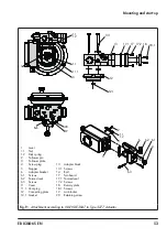
Mount the positioner on the NAMUR rib
2. For
attachment to the NAMUR rib
, fas-
ten the NAMUR connection block (10)
directly into the existing yoke bore using
the screw and toothed lock washer (11).
Align the marking on the NAMUR valve
connection (on the side marked '1') to
50 % travel.
For attachment to
valves with rod-type
yokes
using the formed plate (15), which
is placed around the yoke: screw the four
studs into the NAMUR connection block
(10). Place the NAMUR connection block
on the rod and position the formed plate
(15) on the opposite side. Use the nuts
and toothed lock washers to fasten the
formed plate onto the studs. Align the
marking on the NAMUR valve connec
-
tion (on the side marked '1') to 50 %
travel.
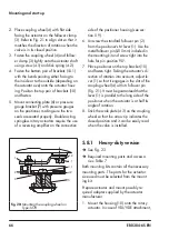
3. Place the adapter bracket (6) on the po-
sitioner and mount using the screws
(6.1). Make sure that the seals are cor-
rectly seated. For positioners
with air
purging
, remove the stopper (5) before
mounting the positioner. For positioners
without air purging
, replace the screw
plug (4) with a vent plug.
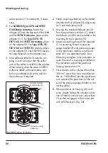
4. Select required lever size (1) M, L or XL
and pin position according to the actua-
tor size and valve travel listed in the trav-
el table on page 28.
Should a pin position other than position 35
with the standard M lever be required or an
L or XL lever size be required, proceed as
follows:
−
Fasten the follower pin (2) in the as-
signed lever hole (pin position as speci-
fied in the travel table). Only use the lon
-
ger follower pin (2) included in the
mounting kit.
−
Place the lever (1) on the shaft of the po-
sitioner and fasten it tight using the disk
spring (1.2) and nut (1.1).
−
Move lever once all the way as far as it
will go in both directions.
5. Insert the molded seal (6.2) in the groove
of the adapter bracket.
Summary of Contents for TROVIS SAFE 3730-6
Page 12: ...12 EB 8384 6S EN...
Page 16: ...16 EB 8384 6S EN...
Page 22: ...22 EB 8384 6S EN...
Page 40: ...40 EB 8384 6S EN...
Page 42: ...42 EB 8384 6S EN...
Page 82: ...82 EB 8384 6S EN...
Page 90: ...90 EB 8384 6S EN...
Page 96: ...96 EB 8384 6S EN...
Page 132: ...132 EB 8384 6S EN...
Page 152: ...152 EB 8384 6S EN...
Page 155: ...EB 8384 6S EN 155...
Page 156: ...156 EB 8384 6S EN...
Page 157: ...EB 8384 6S EN 157...
Page 158: ...158 EB 8384 6S EN...
Page 159: ...EB 8384 6S EN 159...
Page 160: ...160 EB 8384 6S EN...
Page 161: ...EB 8384 6S EN 161...
Page 162: ...162 EB 8384 6S EN...
Page 163: ...EB 8384 6S EN 163...
Page 164: ...164 EB 8384 6S EN...
Page 165: ...EB 8384 6S EN 165...
Page 166: ...166 EB 8384 6S EN...
Page 167: ...EB 8384 6S EN 167...
Page 182: ...182 EB 8384 6S EN...
Page 183: ...EB 8384 6S EN 183...


