


EB 8310-1 EN
25
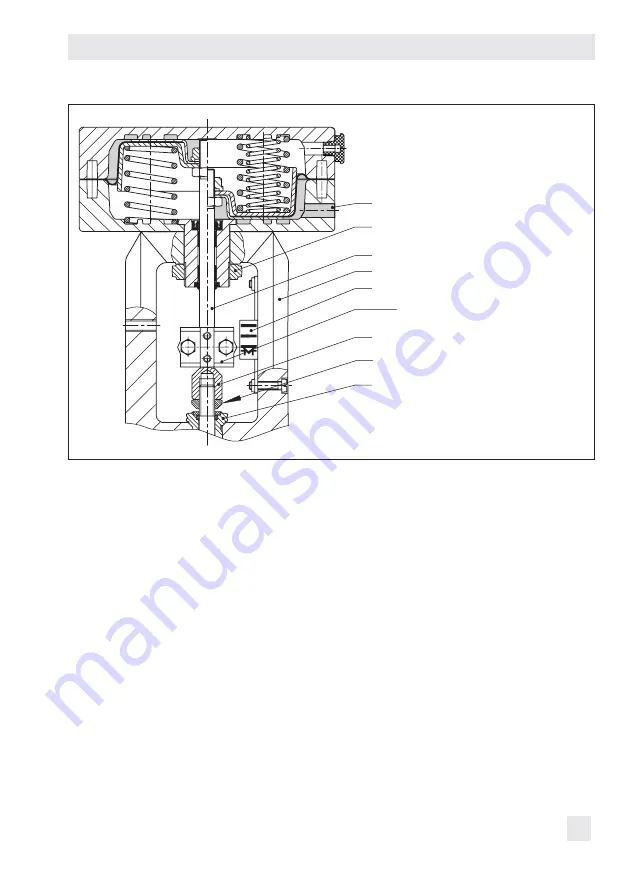
Mounting and start-up
2
84
10
A26/27
9
8
A8
A7
S
2
Bonnet/flange
8
Threaded bushing
9
Stem connector nut
10
Lock nut
84
Travel indicator
scale
A7
Actuator stem
A8
Ring nut
A26/27 Stem connector
clamps
S
Signal pressure
connection
Fig. 5:
Type 3271 Pneumatic
Actuator on a Series 240
Valve
6. Place the actuator onto the valve bonnet
(2) and secure it with the ring nut.
7. Determine the lower and upper signal
pressure range values.
The lower signal pressure range value
corresponds to the minimum value of the
bench range or operating range (see
section 5.3 for adapted travel range).
The upper signal pressure range value
corresponds to the maximum value of the
bench range or operating range (see
section 5.3 for adapted travel range).
8. Connect the signal pressure. See sec-
tion 5.2.
9. Screw on the stem connector nut (9) by
hand until it touches the actuator stem
(A7).
10. Turn the stem connector nut a further
quarter turn and secure this position with
the lock nut (10).
11. Position clamps of the stem connector
(A26/27) and screw them tight.
12. Align the travel indicator (84) with the tip
of the stem connector clamp.
Summary of Contents for 3271-5
Page 11: ...EB 8310 1 EN 11 Markings on the device...
Page 19: ...EB 8310 1 EN 19 Design and principle of operation...
Page 23: ...EB 8310 1 EN 23 Preparation...
Page 45: ...EB 8310 1 EN 45 Malfunctions...
Page 51: ...EB 8310 1 EN 51...


