EB 8048 EN
43
Servicing
9. Mount actuator. See associated actuator
documentation.
10. Adjust lower or upper signal bench
range. See associated actuator docu-
mentation.
11.
Put the control valve back into operation
(see section 6). Make sure the require
-
ments and conditions for start-up or put-
ting the valve back into operation are
met.
9.4 Service work
Î
Before performing any service work,
preparations must be made to the control
valve (see section 9.2).
Î
After all service work is completed, check
the control valve before start-up (see sec-
9.4.1 Replacing the
diaphragm and plug
1.
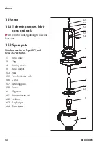
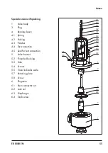
Unscrew the grub screw (6.4).
2. Unscrew the plug stem (6) from the plug
(3).
3. Remove the diaphragm (6.3).
4.
Apply a suitable lubricant (order no.
1400-6991) to the thread of the plug
stem (6).
5.
Screw a new plug (3) onto the plug stem
(6) using a suitable tool. Observe tight-
ening torques.
Valve size
Tightening
torque in Nm
DN
NPS
15 to 25
½ to 1
10
32 to 100
1¼ to 4
70
6. Mark the side mounting position.
7. Remove the plug stem (6) again from the
plug (3).
8.
Insert a new diaphragm (6.3) into the
new plug (3).
9.
Screw the new plug (3) back onto the
plug stem (6) again using a suitable tool.
Align the plug stem with the mounted po-
sition mark made earlier. To do this,
clamp the plug into a suitable clamping
fixture and pull it with a suitable tool.
10.
Remove the mounting position mark.
11.
Secure the plug (3) with the grub screw
(6.4).
12.
Clamp the plug stem (6) into a suitable
chuck.
13. Check the concentricity of the plug (3) to
the plug stem (6). Observe the values list-
14.
If the concentricity deviates, use a suit-
able tool (e.g. plastic hammer) and hit
the plug until concentricity is achieved.
Instead of aligning the plug, the assembly
(consisting of plug stem, diaphragm and
plug) can be ordered from SAMSON.
Tip

