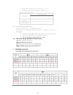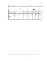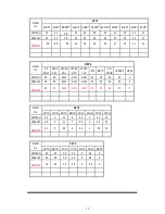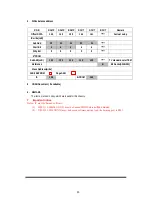
4. White balance address
R G B
R AMP
G AMP
B AMP
R CUT
G CUT
B CUT
Remark
Offset DATA
142
143
150
146
161
*****
Factual setup
IC write(LsB)
Sub Add
32
33
34
23
24 *****
Start Bit
6
6
6 6 6 *****
St0p Bit
0
0
0 0 0 *****
E
2
PROM
Sub Add(LsB)
122
123
124
119
120
*****
TV standard color TEM
Reference
B BJ
SanAi(SWB-301)
Slave Address(write)
16 Bit EEPROM
Page
Addr
IC
138
E
2
PROM
160
5. CDRH Document ( If available)
6. REMARK
The items, marked in Grey, which are invalid for this chassis.
7 Important notice
Below IC must be burned software:
(1) IC001 (13-00M24C-XXP): must be burned EDID before
surface mount;
(2) IC200 (13-P120XXXX):must be burned software online. And the burning port is P003
20
Summary of Contents for SC-29FAS
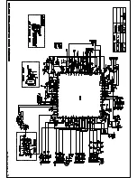
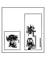
Page 22: ...5 Schematic Diagram ...
Page 23: ......
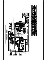
Page 24: ...24 ...
Page 25: ......
Page 26: ......
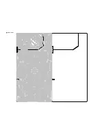
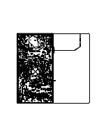
Page 29: ...7 PCB Layout ...
Page 30: ......
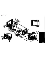
Page 31: ...31 8 Explode View Diagram ...

