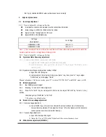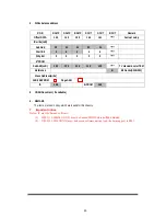
2.7.2 Horizontal geometry adjustment
a. Input a PAL cross hatch pattern with black and white background signal.
b. Press key “3” enter Horizontal geometric adjustment.
c. Use remote control to adjust one by one , watch the figure, until the center and the vertical
line at left and right side of the picture become straight.
Remark
:
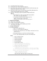
1. Adjust 5HSH for horizontal position, data should make H center mediacy .
2. 5PAR for parallelogram adjustment.
3. 5BOW for bow adjustment.
4. Adjust 5EWW for horizontal width.
5. 5EWP for pincushion correction.
6. 5UCR for upper corner correction.
7. 5LCR for low corner correction.
8. 5EWT for trapezium correction.
* Apply NTSC signal to adjust these registers for NTSC geometric
2.8 EHT/HEW ratio test
:
(
test with PC program
)
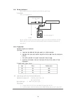
Equipment requirements
:
High Voltage Meter (Range: 0 - 40kV)
、
High voltage test
stick (1000:1)
、
Adjustable DC power supply
、
Dummy deflexion coil(as same inductance as
CRT which use to product).
Test method
:
a. Mount the EHT cap onto the fixture and connect the EHT meter. Plug in
the dummy deflection coil. Connect the DC meter across C417.
b. Switch on the chassis and measure the ratio of EHT/HEW at I
b
= 0
( brightness
、
contrast are minimum).
Here, the HEW is the DC voltage across C417.
EHT voltage V, HEW voltage V1.
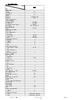
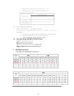
c. Apply PC program, V/V1 need satisfy request below
:
2.9
X rays over voltage protecting circuit test
Test method
:
When TV ON with color bar signal, add more than 27V DV to C417, machine
could enter into protection mode, otherwise please inspect X rays over voltage
protecting circuit .
EHT/HEW (V/V1)
29276SQ 44-29RFLS-OR3A
A68QDL082X012(B)
13
Summary of Contents for SC-29FAS
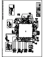
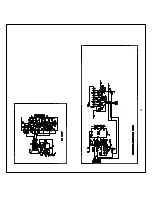
Page 22: ...5 Schematic Diagram ...
Page 23: ......
Page 24: ...24 ...
Page 25: ......
Page 26: ......
Page 29: ...7 PCB Layout ...
Page 30: ......
Page 31: ...31 8 Explode View Diagram ...


