c.
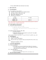
Measure the EHT-voltage at zero beam current (I
beam
= 0
µ
A).
d.
Subsequently, measure the EHT-voltage at respective I
beam(s) .
It should satisfy request below
:
2.13 Heater voltage test ( random test )
Equipment requirements :
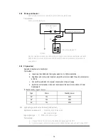
True RMS Voltmeter
Input signal type
:
Philips test card ( from
1 mV rms
(
60dBuV
)
to 50 mV rms )
Test method
:
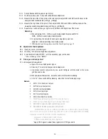
a. Connect the true RMS voltmeter between the heater and grand.
b. Adjust the brightness and contrast to maximum .
c. Then, test the heater voltage . It may be Vrms
2.14 Main function test (eg, NICAM, BTSC, TELTEXT and etc.)
NICAM test standard please reference
BTSC test standard please reference
TELTEXT test standard please reference Q/WP1259-2003.
CCD
、
V-CHIP test standard please reference EIA-744-A
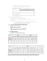
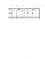
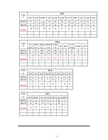
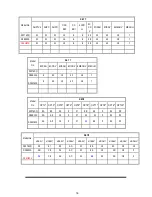
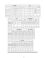
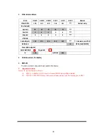
3. EEPROM Data and Address
Items marked with * are adjustable, the others are not.
KEY1 KEY2
Model
No.
RED* GRN* WPR* WPB* WPG* 5VPOS* 5VAM* 5VSL* 5VL* 5VSC
29276SQ 32 26 35 23 33 32
21 33 30 31
S29E12K
32
32
32
32
32
32 21 33
30
31
S29M62K 30 28 37 37 30
32
19 28 30 31
KEY2
Model
No.
5SCL* 5WBF* 5WBR* 5BSWBF* 5BSWBR* 6VPOS* 6VAM* 6VSL* 6VL* 6VSC
29276SQ
31 11 15 9
8 37 25 32 32 31
S29E12K
31 11 15 9
8 37 25 32 32 31
S29M62K
44 11 15 8
5
35
25 32 32 31
Beam current
EHT-voltage (KV)
I
b
= 50
µ
A
I
b
=50
µ
A&1200
µ
A
15
Summary of Contents for SC-29FAS
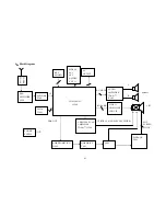
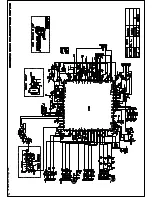
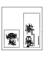
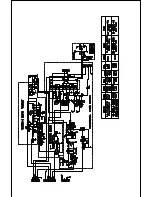
Page 22: ...5 Schematic Diagram ...
Page 23: ......
Page 24: ...24 ...
Page 25: ......
Page 26: ......
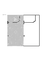
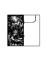
Page 29: ...7 PCB Layout ...
Page 30: ......
Page 31: ...31 8 Explode View Diagram ...


