6
854 815 R. 12/21
SAMOA Industrial, S.A. · Pol. Ind. Porceyo, I-14 · Camino del Fontán, 831 · 33392 - Gijón - Spain · Tel.: +34 985 381 488 · www.samoaindustrial.com
2021_12_16-12:00
EN
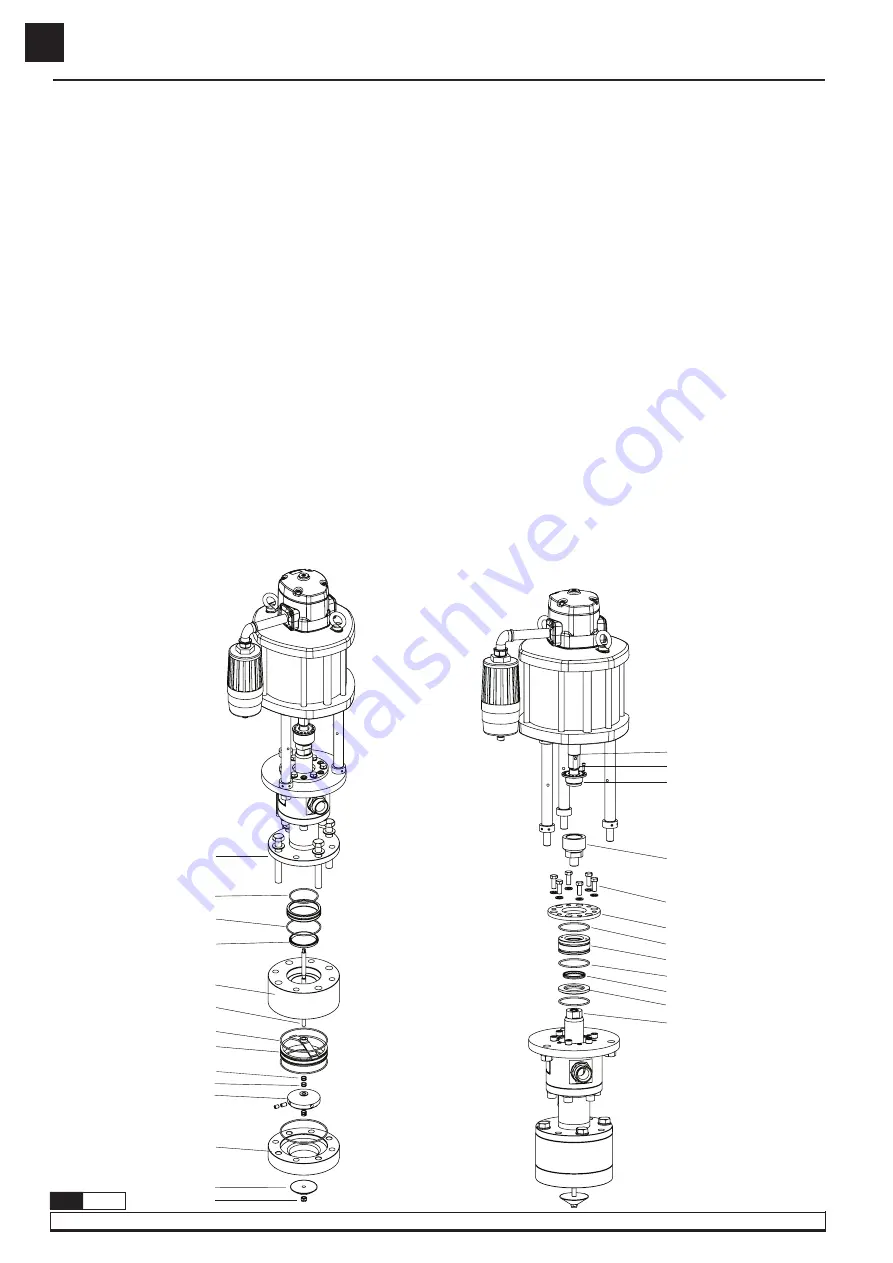
CLEAN OR REPLACE THE FOOT VALVE
ATTENTION:
on this procedure is necessary lift the pump.
1.
Fasten the priming rod in lower part (115) and unscrew the nyloc nut (117). Remove the priming valve (116).
2.
Unscrew the bolts (102) and remove the pump from inlet body (105).
3.
Remove the inlet body (105) and valve guide (107).
4.
Remove the disc valve (110). Examine the valve (110), the U-seat in foot valve (114) and priming rod (115) for any damage. Replace if it’s necessary.
5.
Replace the O-rings (108), back-up rings (109). Fit a new O-ring (71, 83) and compressible spacer (104).
6.
Assembly the foot valve following this section, reversing each step. Apply Loctite 243 on thread (102).
It is also available a whole foot valve kit (754955) with all components in disk valve assembled.
CLEAN OR REPLACE THE PACKING NUT
1.
Using the air motor, stop the pump in the lower down stroke. Release the pump pressure.
2.
Remove the bolt (63) and unscrew the nut (64).
3.
Using air motor, raire gently the air motor rod (47) until upper upstroke. Close the air.
4.
Remove the coupling (67), the bolts (68) and gland top plate (70).
5.
Fit two M5 bolts in the bearing (72) and pull out. The u-seal (73) should be stayed with the packing nut, if it stayed in the pump, slide it up
the packing rod (91) gently until is free.
6.
Examine the packing nut (72) and the rod (91) for wear and or damage as if they are defective any new packing rod seal will fail. If the nut
is faulty this will replaced now, but if the rod is faulty the pump will have to be completely dismantled (please, follow the section clean and
replace piston valve).
7.
Fit a new o-seal (71). Replace the packing rod seal (73) to the packing nut (72), lightly greasing the seals to aid assembly.
8.
Push the nut (72) and seal over the packing rod (91) until the U-seal stop (74). Apply Loctite 243 on thread (67, 68). Assemble the pump
following this section, reversing each step.
REPAIR AND CLEANING PROCEDURE
Fig. 10
47
63
64
67
68
70
71
72
71
73
74
91
Fig. 9
102
71
83
104
105
115
106
107
108
109
110
114
116
117


