background image

3

R. 05/21  850 823

 SAMOA Industrial, S.A. · Pol. Ind. Porceyo,  I-14 · Camino del Fontán, 831 · 33392 -  Gijón - Spain · Tel.: +34 985 381 488 · www.samoaindustrial.com

2021_05_03-13:00

EN

NOTE:

 During hose installation, tighten the U-bolt just till the hose gets 

slightly deformed. Do not overtighten the U-bolt, since the hose could 
be damaged.

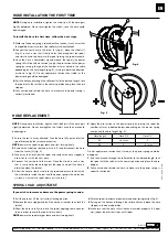
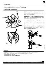
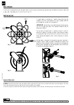
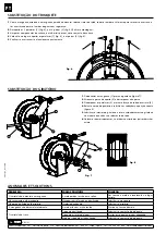
To install the hose the first time, follow the next steps:

1.

 Make sure the power spring is relaxed, with no tension, in such a way that 

the spool does not try to turn (the ratchet must be unlocked).

2.

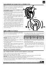
 Connect the new hose to the swivel (2) (fig. 4), place the U-bolt (1) 

(fig. 4) in such a way that it firmly holds the hose against the spool, 
and start to wind the hose into the spool turning the spool manually.

3.

 Once the hose is completely wound around the spool (the power 

spring still will be with no tension), apply the pre-tension to the power 
spring by turning the spool the number or turns stated in the table 
depending on the hose length (pag. 5), turning in positively direction 
as shown in (fig. 5). Do not apply more tension than stated, as the 
power spring could be damaged.

4. 

Pass the hose end through the roller outlet to the desired length, lock 
the spool with the ratchet in the nearest position and place the hose 
stopper.

5.

 Fully unwind and rewind the hose to make sure the power spring is 

correctly tensioned.

HOSE INSTALLATION THE FIRST TIME

Fig. 5

Fig. 4

2

1

NOTE:

 During hose installation, tighten the U-bolt just till the hose gets 

slightly deformed. Do not overtighten the U-bolt, since the hose could 
be damaged.

1. 

Ensure the reel is firmly attached. Take the hose fully out and let the 
spool blocked by the ratchet mechanism.

NOTE:

 beware the spool to get loose and start turning freely.

2. 

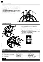
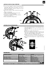
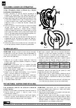
Remove the U-bolt by loosening its nuts (1) and disconnect the hose 
from the swivel (2) (fig. 4).

3. 

Take away the hose from the spool and remove the hose stopper in 
order to use it with the new hose.

4. 

Connect the new hose to the swivel. Place the U-bolt in such a way 
that it firmly holds the hose against the spool, and pull the hose in 
order to unlock the ratchet.

5.

 Allow the hose to slowly wind into the spool and ensure to finish with 

the whole hose inside the reel and the power spring with no tension 
(in such a way that the spool does not try to turn).

6.

 Apply the pre-tension to the power spring by turning the spool the 

number of turns indicated below, depending on the power spring 
version and the hose length (fig. 5):

Hose length

Hose 3/4"

Hose 1/2"

50'

+8 turns

X

65'

X

+4 turns

Do not apply more tension than stated, as the power spring could be 
damaged.

7.

 Pass the hose end through the roller outlet to the desired length, lock 

the spool with the ratchet in the nearest position and place the hose 
stopper.

8.

 Fully unwind and rewind the hose to make sure the power spring is 

correctly tensioned.

HOSE REPLACEMENT

If you wish to increase or decrease the power spring tension:

1.

 Pull the hose out till the first ratchet locking position.

2.

 Remove the hose stopper and pull the hose out in order to unlock the 

ratchet.

3.

 Allow the hose to fully wind into the spool, applying some counter-

force in order to avoid the spool to turn freely.

NOTE: 

beware the spool may get loose and start turning freely.

SPRING LOAD ADJUSTMENT

4.

 Turn the spool to increase or decrease the power spring tension (fig. 5).

5.

 Pass again the hose end through the roller outlet and place the hose 

stopper in the desired position.

6.

 Make sure that the hose fully winds and unwinds properly. If it does 

not, repeat the previous steps until it does.

Summary of Contents for 505 Series

Page 1: ...ES 505 Parts and technical service guide Gu a de servicio t cnico y recambio Guide d instructions et pi ces de rechange Bedienungsanleitung und Teileliste Manual de Servi os T cnicos e Reposi es HIGH...

Page 2: ...loose from the reel frame Then just position the guide arms in the desired position and fix them with the same screws To position the hose stopper take out the hose to the nearest blocking ratchet po...

Page 3: ...he spool to get loose and start turning freely 2 Remove the U bolt by loosening its nuts 1 and disconnect the hose from the swivel 2 fig 4 3 Take away the hose from the spool and remove the hose stopp...

Page 4: ...2 fig 7 2 Loosen the set screw in the nut 3 and remove said nut 3 Remove the screws 4 and the arm 5 4 Remove the swivel and replace it with a new one or replace the seals Make sure the seals are place...

Page 5: ...r los brazos a la posici n deseada y a volver a fijarlos con los mismos tornillos Para posicionar el tope de manguera desenrolle la manguera hasta llegar a la posici n de bloqueo del trinquete m s pr...

Page 6: ...en la tabla dependiendo de la longitud de la manguera p g 6 en sentido positivo seg n fig 5 No se debe aplicar m s tensi n de la indicada pues el resorte podr a resultar da ado 4 Pase el extremo de l...

Page 7: ...ensi n o se ha roto Dar tensi n al resorte o reemplazarlo La manguera pierde fluido Manguera con poro o rota Cambiar la manguera La r tula pierde fluido R tula deteriorada Cambiar la r tula La manguer...

Page 8: ...but e de blocage du flexible d rouler celui ci jusqu atteindre la position de verrouillage du cliquet la plus proche de la longueur d sir e Desserrez la but e glissez la dans la position souhait e et...

Page 9: ...l cher le cliquet et que l enrouleur commence tourner librement 2 Retirez les boulons en U en desserrant leurs crous 1 et d branchez le flexible de la rotule pivotante 2 fig 4 3 Retirez le flexible du...

Page 10: ...e ressort a perdu de la tension ou s est rompu Augmenter la tension du ressort ou le remplacer Fuite sur le flexible Flexible poreux ou cass Remplacer le flexible Fuite de la rotule La rotule est d t...

Page 11: ...ebenen Oberfl che befindet Boden Werkbank etc Um die F hrungsarme in die gew nschte Stellung zu bringen m ssen die Schrauben 1 Abb 2 an beiden Armen gel st und entfernt werden so dass die Trommel zus...

Page 12: ...drehen kann 2 Entfernen Sie den Bolzen indem sie die Muttern 1 mit denen er befestigt ist l sen und trennen Sie den Schlauch mittels zweier Schl ssel vom Drehgelenk 2 Abb 4 3 Ziehen Sie den Schlauch a...

Page 13: ...nicht ein Die Trommelfeder hat ihre Spannung verlo ren oder ist defekt Die Trommelfeder nachspannen oder aus tauschen Der Schlauch ist undicht Por ser oder defekter Schlauch Schlauch austauschen Das D...

Page 14: ...Para posicionar os bra os guia necess rio afrouxar e retirar os parafusos 1 figura 2 de ambos os bra os Neste momento a roda e os bra os guia estar o soltos da base neste momento Ent o trocar os bra o...

Page 15: ...livremente 2 Retirar o fixador afrouxando as porcas 1 e desconectando a mangueira do girat rio 2 figura 4 3 Extrair a mangueira da roda e desmontar a abra adeira de parada da mangueira afrouxando os...

Page 16: ...se soltou Dar tens o a mola ou recoloca la no lugar correto H vazamento pela mangueira Mangueira est furada ou danificada Substituir a mangueira H perda de fluido pelo girat rio Girat rio danificado S...

Page 17: ...17 R 05 21 850 823 SAMOA Industrial S A Pol Ind Porceyo I 14 Camino del Font n 831 33392 Gij n Spain Tel 34 985 381 488 www samoaindustrial com 2021_05_03 13 00 RU 7 1 1 2 3 1 15 3 4 20 1 2 3 U U 2 1...

Page 18: ...ial S A Pol Ind Porceyo I 14 Camino del Font n 831 33392 Gij n Spain Tel 34 985 381 488 www samoaindustrial com 2021_05_03 13 00 RU 5 4 2 1 1 2 3 4 5 5 6 1 2 2 4 U 1 4 3 5 5 4 5 U U 1 2 U 1 2 4 3 4 U...

Page 19: ...Industrial S A Pol Ind Porceyo I 14 Camino del Font n 831 33392 Gij n Spain Tel 34 985 381 488 www samoaindustrial com 2021_05_03 13 00 RU 8 2 1 3 7 3 4 4 5 1 1 2 7 2 3 3 4 5 4 8 5 6 1 2 2 1 6 4 2 6...

Page 20: ...ndustrial S A Pol Ind Porceyo I 14 Camino del Font n 831 33392 Gij n Spain Tel 34 985 381 488 www samoaindustrial com 2021_05_03 13 00 560 220 130 1 0 DIMENSIONS DIMENSIONES DIMENSIONS ADMESSUNGEN DIM...

Page 21: ...Spain Tel 34 985 381 488 www samoaindustrial com 2021_05_03 13 00 PARTS LIST LISTA DE RECAMBIOS PI CES DE RECHANGE TEILELISTE PE AS DE REPOSI O 1 2 3 4 5 6 7 8 9 10 11 12 13 16 17 18 19 528021 525020...

Page 22: ...ja media presi n Axe court 3 4 BSP pour basse moyenne pressi n NOTE All the hose reels following September 2015 must mount the short shaft Pos 17 NOTA Todos los enrolladores posteriores a Septiembre d...

Page 23: ...e Achse 3 4 BSP f r durchnitt niedriger Eixo corto 3 4 BSP para para m dio baixa press o 3 4 BSP HINWEIS Alle Schlauchaufroller nach September 2015 sind mit der kurzen Achse ausgestattet Pos 17 NOTA T...

Page 24: ...o del Font n 831 33392 Gij n Espagne d clare que ce produit est conforme au Directive de l Union Europ enne 2006 42 CE FR SAMOA INDUSTRIAL S A Pol Ind Porceyo I 14 Camino del Font n 831 33392 Gij n Sp...

Reviews: