


SAM4S NR-500 SERIES
4-1
4 Disassembly and Assembly
Caution :
· Before installation, be sure to turn off the power switch.
· Use gloves to protect your hand from being cut by the angle and the chassis.
· Connect all the cables correctly. When connecting or disconnecting the cables, be careful not to apply
stress to the cables. (It may cause disconnection)
· Be careful not to bind interface cables and AC power cord together.
Note :
Before disassembling, first of all separate the ASS'Y CASE UPPER(B) from the ASS'Y CASE
LOWER(E)
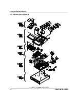
4-1 Disassembling the Case Upper Block
4-1
A. Ass’y Case Upper
1. Open the ASS'Y COVER PRINTER(A) and lift it off. (Page6-1,Page6-2)
2. Remove the four screws(B15:3pcs, B16:1pcs) from the ASS'Y CASE LOWER(E).(Page6-1, 6-3)
3. Separate the three harnesses(
Û
,
Ü
,
Ý
) from the PBA-MAIN BOARD(E4). (Page6-1, 6-3, 6-13)
4. Lift off the ASS'Y CASE UPPER(B) from the ASS'Y CASE LOWER(E). (Page6-1, 6-3, 6-13)
4-1
B. Ass’y Front Display(LCD)
1. Separate the harness(
Ü
) from the PBA-MAIN BOARD(E4). (Page 6-13)
2. Remove the two screws(B29) from the ASS’Y CASE UPPER(B).(Page6-3)
3. Separate the ASS’Y LCD(B6) from the ASS’Y CASE UPPER(B).(Page6-3)
4. Remove the four screws(B7) from the ASS’Y LCD(B6).(Page6-3)
5. Separate the PMO-FRONT LCD(B15) and the LCD(B14) from the ASS’Y LCD(B6).(Page6-3)
6. Separate the harness(
Ü
) from the LCD(B14) .(Page6-3)
7. Remove the two screws(B11,B13) from ASS’Y LCD(B6). (Page6-3)
8. Separate the PMO-REAR LCD(B9), the PMO-HOLDER LCD(B17) and the HINGE(B12).(Page6-3)
4-1
C. Ass’y Rear (Turret) Display
1. Separate the harness(
Ý
) from the PBA-MAIN BOARD(E4). (Page 6-13)
2. Separate the PMO-TURRET BODY (B24) from the ASS'Y CASE UPPER (B). (Page6-3)
3. Remove the two screws(B20) PMO-HOLDER LCD REAR(B23).(Page6-3)
4. Separate the LCD(B21), PMO-HOLDER LCD REAR(B23) from the PMO-TURRET BODY (B24).
(Page6-3)
5. Separate the harness(
Ü
) from the LCD(B21).(Page6-3)
4-1
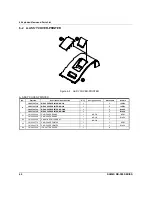
D. Ass’y Cover Mode Switch
1. Separate the ASS'Y COVER MODE S/W(B1) from ASS'Y CASE UPPER(B).(Page6-3)
2. Remove the two screws(B5) on the ASS'Y COVER MODE S/W(B1) and
separate the MODE KEY ASS’Y(B4) from the PMO-COVER MODE S/W(B1). (Page6-3)
3. Remove the two screws(B2) on the MODE KEY ASS’Y(B4) and separate the
IPR-BRKT MODE S/W(B3) and the MODE KEY ASS’Y(B4). (Page6-3)
Summary of Contents for NR-500R
Page 18: ...2 Product Specifications 2 12 SAM4S NR 500 SERIES MEMO...
Page 23: ...3 Installation and Operation SAM4S NR 500 SERIES 3 5...
Page 36: ...5 Maintenance and Adjustment 5 2 SAM4S NR 500 SERIES MEMO...
Page 57: ...6 Exploded Views and Parts List SAM4S NR 500 SERIES 6 21 MEMO...
Page 58: ...SAM4S NR 500 SERIES 7 1 7 PCB Layout and Parts List 7 1 Main PCB Layout...
Page 74: ...8 Troubleshooting 8 8 SAM4S NR 500 SERIES MEMO...
Page 76: ...9 Block Diagram 9 2 SAM4S NR 500 SERIES MEMO...
Page 77: ...SAM4S NR 500 SERIES 10 1 10 Wiring Diagram 10 1 Wiring Pin Connection...
Page 80: ...10 Wiring Diagram 10 4 SAM4S NR 500 SERIES MEMO...
Page 101: ......
Page 102: ...Shin Heung Precision Oct 2017 Printed in KOREA V1 6...