3 Installation and Operation
3-10
SAM4S NR-500 SERIES
3-3
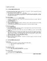
E. Self Test
Before the test. You will find ‘SELF TEST’ menu.
1. Move to the
SERVICE MODE
.
2. Press the ‘
1
’ to select ‘SELF TEST’.
3-3
E-(a) Test Printer
1. From the SELF TEST menu, Press ‘
2
’ to select PRINTER.
2. From the PRINTER menu, Press ‘
1
’ to select PRINT TEST.
3. After printing, The drawer is opened. Then the printer test is finished.
4. Press the ‘
CLEAR’
key to return to SELF TEST menu.
3-3
E-(b) Test Display
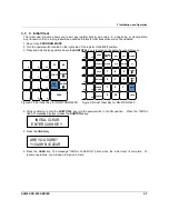
1. From the SELF TEST menu, Press ‘
3
’ to select DISPLAY.
2. From the DISPLAY menu, Press ‘
1
’ to select LCD TEST.
3. Press the ‘
CASH
’ key 2 times to finish LCD TEST.
4. Press the ‘
CLEAR
’ key to return to SELF TEST menu.
3-3
E-(c) Test Key Board
1. From the SELF TEST menu, Press ‘
4
’ to select KEYBOARD.
2. From the KEYBOARD menu, Press ‘
1
’ to select KEYBOARD TEST.
3. Press any key you want on the key board.
4. The key name of pressed key will be showed on the LCD.
5. Press the ‘
CLEAR
’ key to return to SELF TEST menu.
3-3
E-(d) Test Mode Switch
1. From the SELF TEST menu, Press ‘
4
’ to select KEYBOARD.
2. From the KEYBOARD menu, Press ‘
2
’ to select MODE KEY TEST.
3. Turn the mode switch to any position.
4. The corresponding Mode name will be showed on the LCD.
5. Press the ‘
CLEAR
’ key to return to SELF TEST menu.
3-3
E-(e) Test SERIAL1 (COM1)
1.
From the SELF TEST menu, Press ‘
5
’ to select INTERFACE.
2.
Install the serial loop back test jig. (Short “pin 2 , 3” , ” pin 4 , 6” ) of DSUB connector.
3.
From the INTERFACE menu, Press ‘
1
’ to select SERIAL 1.
4.
If error occurs, the message “ ** NG ** “ is displayed on LCD and the Buzzer beep.
5.
Press the ‘
CLEAR
’ key to return to SELF TEST menu.
3-3
E-(f) Test SERIAL2 (COM2)
1.
From the SELF TEST menu, Press ‘
5
’ to select INTERFACE.
2.
Install the serial loop back test jig. (Short “pin 3 , 4” , ” pin 2 , 8” ) of RJ-45 connector.
3.
From the INTERFACE menu, Press ‘
2
’ to select SERIAL 2.
4.
If error occurs, the message “ ** NG ** ” is displayed on LCD and the Buzzer beep.
5.
Press the ‘
CLEAR
’ key to return to SELF TEST menu.
SELF TEST
1. BATCH TEST
2. PRINTER
3. DISPLAY
4.KEYBOARD
5.INTERFACE
6.RTC
Figure3-11 SELF TEST MENU
Summary of Contents for NR-500R
Page 18: ...2 Product Specifications 2 12 SAM4S NR 500 SERIES MEMO...
Page 23: ...3 Installation and Operation SAM4S NR 500 SERIES 3 5...
Page 36: ...5 Maintenance and Adjustment 5 2 SAM4S NR 500 SERIES MEMO...
Page 57: ...6 Exploded Views and Parts List SAM4S NR 500 SERIES 6 21 MEMO...
Page 58: ...SAM4S NR 500 SERIES 7 1 7 PCB Layout and Parts List 7 1 Main PCB Layout...
Page 74: ...8 Troubleshooting 8 8 SAM4S NR 500 SERIES MEMO...
Page 76: ...9 Block Diagram 9 2 SAM4S NR 500 SERIES MEMO...
Page 77: ...SAM4S NR 500 SERIES 10 1 10 Wiring Diagram 10 1 Wiring Pin Connection...
Page 80: ...10 Wiring Diagram 10 4 SAM4S NR 500 SERIES MEMO...
Page 101: ......
Page 102: ...Shin Heung Precision Oct 2017 Printed in KOREA V1 6...


