MD22 INSTRUCTION MANUAL
5
Release system pressure then drain the pipe run where the device
is to be located (it may be necessary to drain the whole system).
When installing below a boiler or other object, allow 250mm
clearance from the top of the canister to beneath the object, to
enable the lid assembly to be removed when servicing.
The device has been designed to facilitate various inlet and outlet
configurations. Most configurations will require Elbows. For
soldering we recommend 28x Yorkshire Solder Ring Elbow
YP1222mm (code08290), or for compression we recommend
2 Yorkshire copper KS61522mm (code 61124K) and the fitting
instructions (which follow) are based around dimensions of these
elbows. For clarity the recommended solder and compression
fittings require the same dimension of cutout.
Vertical pipe run:
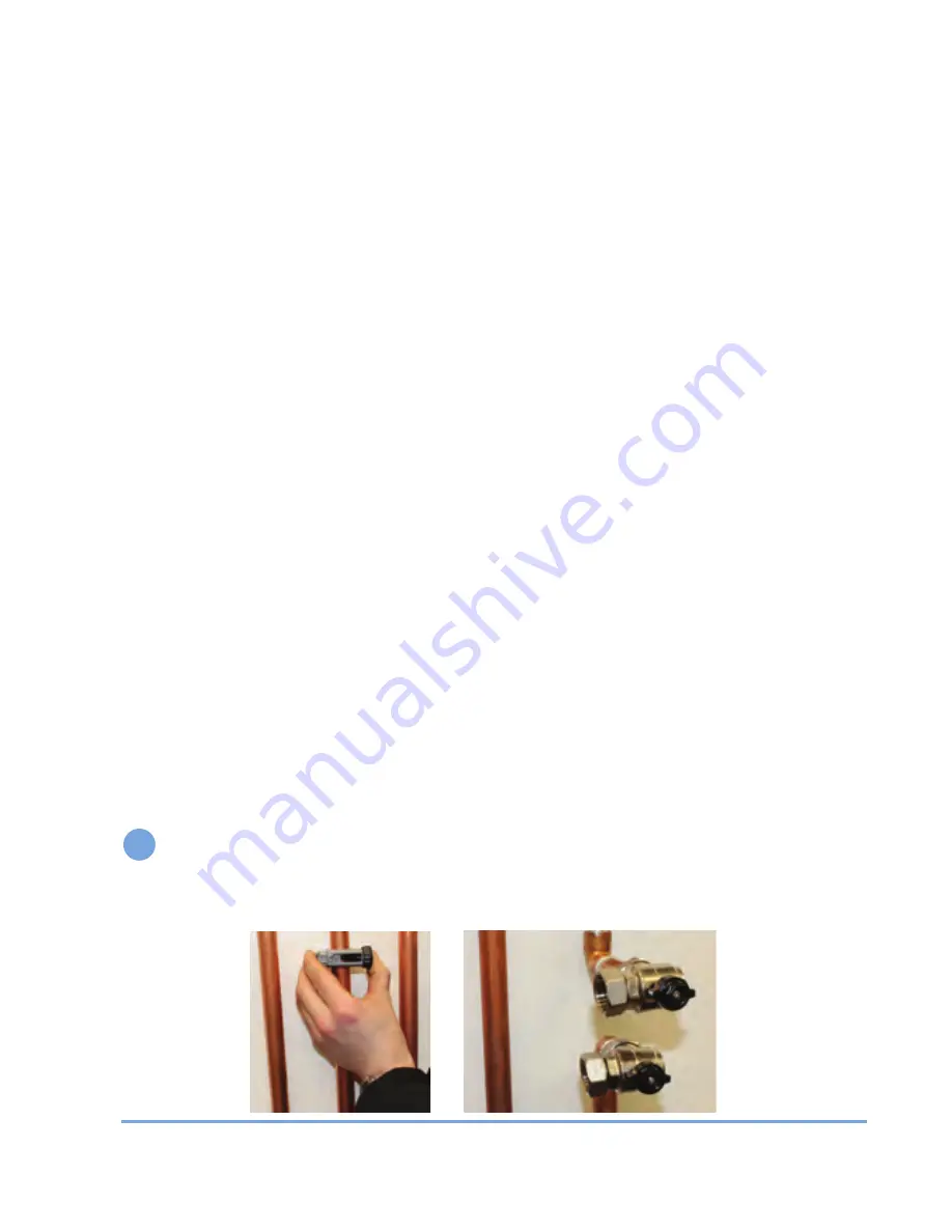
Measure and mark a 110mm section for a
22mm unit, as shown below. Remove this marked section using a
pipe cutter as shown. Now create 64mm and 106mm of 22mm
copper pipe to attach between the respective elbow and
compression fitting on the inlet/outlet. Tip: Reuse the cut out
section.
Horizontal pipe runs:
Measure and mark 73mm section and
remove the marked section with a rotary tube cutter. Create
64mm and 134mm lengths of 22mm copper pip to attach
between the respective elbow and compression fitting on the
inlet/outlet.
Tip:
Reuse the cut out section.
Prepare the pipe and fittings, lubricate the olives and connect
the valves on the pipe work, please only hand tighten the
connections at first.
1
MAG Defender Manual 013_Layout 1 28/02/2013 15:57 Page 6


