S3331 Series Handheld Spectrum Analyzer
User Manual
Saluki Technology Inc.
Page 1: ...S3331 Series Handheld Spectrum Analyzer User Manual Saluki Technology Inc...
Page 2: ...ld spectrum analyzer Item Name Qty 1 Main Machine 1 Set 2 AC DC Adaptor 1 pcs 3 Battery 1pcs 4 CD 1 pcs Options of the S3331 handheld spectrum analyzer Option Number Item S3331 01 Tracking signal sour...
Page 3: ...product meets the indicator requirements of the manual at the time of delivery Calibration and measurement are completed by the measuring organization with qualifications specified by the state and r...
Page 4: ...886 2 2175 2930 Email sales salukitec com www salukitec com 4 Contacts Service Tel 886 2 2175 2930 Website www salukitec com Email info salukitec com Address No 367 Fuxing N Road Taipei 105 Taiwan R...
Page 5: ...15 4 1 Menu Structure 15 4 2 AMP 16 4 3 BW SWP 17 4 4 FREQ 18 4 5 Marker 19 4 6 Meas 21 4 7 Mode 23 4 8 PEAK 27 4 9 Span 28 4 10 System 29 4 11 Trace 30 5 TYPICAL OPERATION 33 5 1 Prepare 33 5 2 Cont...
Page 6: ...nu Bar 51 7 TROUBLE SHOOTING 55 7 1 Start S3331 but the screen does not light 55 7 2 Keys not respond or the response is incorrect 55 7 3 No signal display after normal power on 55 7 4 The frequency o...
Page 7: ...z 7 5GHz DANL 140 dBm for full span min 161dBm typ Phase noise 100 dBc Hz at 100 kHz offset Fast sweep speed 50ms for full span sweep Level accuracy 1 5dB Build In Tracking source Frequency 100kHz 1 5...
Page 8: ...l sales salukitec com www salukitec com Limit Line User defined mask Channel Power OBW Occupied Bandwidth ACPR Adjacent Channel Power Ratio AF FM demodulation Audio demodulation Scalar network measure...
Page 9: ...ly with these instructions accordingly 2 1 Device safety a Use designated packing container in shipping and avoid falling or violent collisions in moving which may cause damages to the device b Use AC...
Page 10: ...need to be trained When using the device concentration is required Operation by unqualified people may cause personal injuries and property losses e Use of this device when power line is broken is pro...
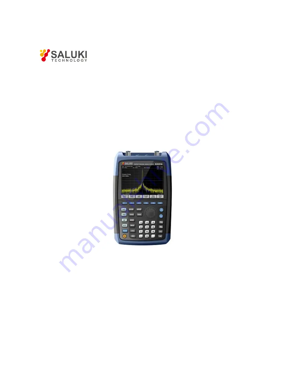
Page 11: ...liar with the basic application of the panel keyboard of the instrument by reading it The front panel of S3331 handheld spectrum analyzer is as shown below Figure 3 1 Front Panel of S3331 handheld spe...
Page 12: ...de RBW VBW average sweep time settings Trace settings Include detector max hold min hold settings Auto measurement Mode settings Include tracking source settings demodulation settings trigger pass fai...
Page 13: ...w salukitec com Figure 3 2 Soft Keys on S3331 3 4 Interfaces on Side Figure 3 3 Side View of S3331 Handheld Spectrum Analyzer No Description No Description External Trigger Input BNC Ear phone interfa...
Page 14: ...Description No Description USB Port Battery hatch 3 5 User Interface Figure 3 4 User Interface of S3331 Handheld spectrum analyzer NO Name Trace Display Format Detector Type Attenuator RBW VBW Trace...
Page 15: ...re of all buttons and soft keys Detail function description will be provided in section 4 2 S3331 has following function keys on front panel Following paragraphs will show the menu structure of these...
Page 16: ...Maximum can be set to 39dB Preamplifier ON OFF Menu description to control the ON OFF status of the preamplifier Preamplifier is provided as a standard component Scale Div Menu description to select t...
Page 17: ...ng keys or knob to change The current mode is shaded Average Menu description to smooth the trace based on the average factor N Sweep time Auto Manual Menu description to change the sweep time of sign...
Page 18: ...the signal spectrum analyzer into the start frequency stop frequency mode Use number keys stepping keys or knob to change the start frequency In changing the start frequency if the selected start freq...
Page 19: ...alue including marker frequency value but this does not affect the sweep span Use number keys stepping keys or knob to change the offset Frequency Ref Menu description to switch between internal refer...
Page 20: ...marker functions The Marker Function performs post processing on the marker data Its soft menu includes Marker Noise ON OFF NdB ON OFF Freq Count Marker Noise On Off Menu description when this menu i...
Page 21: ...erence Level Menu description to set the Reference Level equal to the Marker Amplitude The menu changes the value of reference level Delta Marker Span Menu description to set the Span equaling to freq...
Page 22: ...in Meas Setup ACPR is used to measure the power rate between the adjacent channel and the main channel Channel Power Menu description Turn on channel power measurement function Detailed settings to be...
Page 23: ...23 Tel 886 2 2175 2930 Email sales salukitec com www salukitec com 4 7 Mode...
Page 24: ...g Pass Fail FD Track Gen Menu description to enable and disable the tracking source and make tracking source output settings Tracking source is an option of S3331 series handheld analyzer Track Gen On...
Page 25: ...tion Connect the RF output port to RF input port and press Normalize The track will be a straight line at 0Db DEMOD Menu Description Audio analysis function Support audio signal input from FMW FM AM U...
Page 26: ...or amplitude Freq Line On Off Menu Description Turn on off the vertical limit lines for frequency Window Sweep On Off Menu Description If turn on window sweep only the trace in the limit window is fre...
Page 27: ...rrent test trace Right Peak Menu description to search for the peak to the right of the current test trace marker position Left Peak Menu description to search for the peak to the left of the current...
Page 28: ...n Menu description the span can be set by number keys stepping keys or knob Use number keys or select Zero Span to set the span as zero Full Span Menu description to set the signal spectrum analyzer i...
Page 29: ...enu description To change the language Date Time Menu description To change the time settings PowerOn Preset Menu description To customize the preset configuration File Menu description File operation...
Page 30: ...1 2 3 4 5 Clear Write Max Hold Min Hold Bland View Detector Operation Trace 1 2 3 4 5 Menu description to select trace The signal spectrum analyzer provides 5 trace lines Trace 1 Trace 2 Trace 3 Trac...
Page 31: ...scription to set the detector command for the currently selected trace as Normal i e display the measurement results of positive peak and negative peak at the same time to achieve display effect simil...
Page 32: ...com 2 3 Menu description Exchange the data in trace register 2 and trace register 3 and display 1 3 Menu description Put data in trace register 1 into trace register 3 and display 2 3 Menu description...
Page 33: ...transmitted received via a test cable or a pair of antennas Before any test please ensure power level of input signal should not exceed 30dBm 1W otherwise the instrument would be damaged 5 2 Continuou...
Page 34: ...when the spectrum analyzer receives two signals with equal amplitude and close frequency interval the top of one band pass filter waveform nearly covers another one making two signals like one If two...
Page 35: ...of two signal generators and view the signals displayed on the spectrum analyzer to make the displayed amplitudes of two signals equal 3 Set up the spectrum analyzer to view signals Press Preset Pres...
Page 36: ...than the frequency interval of the two signals same as resolving two signals of equal amplitude But the maximum resolution bandwidth for resolving two signals with different amplitudes mainly depends...
Page 37: ...or of the resolution bandwidth filter of S3331 Handheld Microwave Spectrum Analyzer is 5 1 when the resolution bandwidth is 30kHz the bandwidth on 60dB point is 115kHz the half bandwidth is 57 5kHz wh...
Page 38: ...ollowing example uses a S1103 signal generator and generates a 500MHz 10dBm continuous signal Example 1 Connect the signal generator output port to S3331 RF test port 2 Press Preset key to return the...
Page 39: ...Bandwidth Test Result 5 5 Adjacent Channel Power Following example uses a S1103 signal generator and generates a 500MHz 10dBm continuous signal Example 1 Connect the signal generator output port to S...
Page 40: ...erates a 500MHz 10dBm continuous signal Example 1 Connect the signal generator output port to S3331 RF test port 2 Press Preset key to return the instrument to default status 3 Set test frequency Pres...
Page 41: ...generates a 500MHz 10dBm continuous signal Example 1 Connect the signal generator output port to S3331 RF test port 2 Press Preset key to return the instrument to default status 3 Set test frequency P...
Page 42: ...Example 1 Connect the signal generator output port to S3331 RF test port 2 Press Preset key to return the instrument to default status 3 Set test frequency Press FREQ key Select Center FREQ and input...
Page 43: ...Start FREQ and input 200MHz Select Stop FREQ and input 1GHz The trace will be displayed as shown in the figure below There are 3 peaks signal the second harmonic and the third harmonic 4 Use Peak and...
Page 44: ...ment 5 10 TOI Distortion Measurement In following example use 2x signal generator to generate a 500MHz 10dBm Sine signal and a 501MHz 10dBm sine signal Example 1 Connect the outputs of two signal gene...
Page 45: ...Man and input 1kHz 4 Use Peak and Marker keys to do the analyze Press Peak key S3331 will search the MAX value and mark it with a marker 1 Press Marker key Select Delta a Marker 2 is activated and it...
Page 46: ...Win 7 32bit 64bit 6 2 Software Installation Procedures 1 Copy the installation file zip pack into controller or a PC and un zip it Saluki provide 2 installation for different Operation Systems SALUKI...
Page 47: ...47 Tel 886 2 2175 2930 Email sales salukitec com www salukitec com 4 In following window browse the folder to install the software then click Next...
Page 48: ...k installation wizard will pop out and please follow the wizard and complete the installation 7 If NI VISA foundation is not installed installation wizard will pop out and please follow the wizard to...
Page 49: ...via USB port Connect the USB A type port photo below on the top of the instrument to a PC 10 Install the USB driver When S3331 is connected to PC a driver installation window will pop out If the drive...
Page 50: ...ser can use the Saluki remote control software to manage S3331 LAN connection not only provide SCPI command control but also provide a UI It is a mapping of the keys and display of the S3331 1 Connect...
Page 51: ...s used to display soft menu when any of keys in key zone is pressed The function of this zone is similar to the Soft Keys described in section 3 3 Soft Keys 6 4 3 SCPI control Zone This zone is used t...
Page 52: ...ave the current display as a picture and save locally 6 4 5 2 View View menu is used to set the display of each function zone of the software For example if Ctrl SCPI and Virtualkey is unpicked the so...
Page 53: ...53 Tel 886 2 2175 2930 Email sales salukitec com www salukitec com 6 4 5 3 Device Device menu is main used to control the connection 6 4 5 4 Help Help menu is used to get the software information...
Page 54: ...54 Tel 886 2 2175 2930 Email sales salukitec com www salukitec com...
Page 55: ...y after normal power on If the monitor does not display the signal please follow the steps below 1 Connect 10MHz reference outputs port to RF input port 2 If there is no signal Display there may be ma...
Page 56: ...itude S3331A S3331B Amplitude Maximum safe input level Average continuous power 27dBm 23dBm DC voltage 50Vdc maximum 50Vdc maximum Input attenuator range 0 39dB Steps of 3 dB 0 30dB Steps of 1 dB 1dB...
Page 57: ...Preamp off Preamp on Preamp off Preamp on 100kHz 1MHz 100dBm 3 f 100kHz dB 120dBm 3 f 100kHz dB 95dBm 3 f 100kHz dB 110dBm 3 f 100kHz dB 1MHz 10MHz 130dBm 150dBm 125dBm 140dBm 10MHz 1GHz 135dBm 155dBm...
Page 58: ...equency range 100kHz 1 5GHz 100kHz 3 2GHz Output level 30dBm To 0dBm Stepped by 1 dB 30dBm To 0dBm Stepped by 1 dB Output flatness 3dB 3dB 8 10 General S3331A S3331B Display 6 5 inch TFT LCD 6 5 inch...
Page 59: ...6 2 2175 2930 Email sales salukitec com www salukitec com S3331A S3331B Power adapter Input Voltage 100V 240V 50 60Hz 1 5A Input Voltage 100V 240V 50 60Hz 1 5A Output Voltage 9V 4000mA Output Voltage...
Page 60: ...60 Tel 886 2 2175 2930 Email sales salukitec com www salukitec com Appendix A S3331 Handheld Spectrum Analyzer Programming Manual...