
56
English
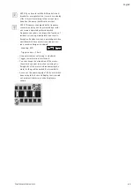
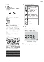
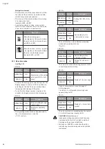
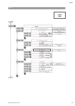
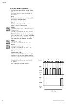
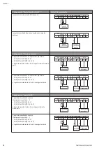
Access lock
In order to lock the pump settings, it is possible
to use the « Access lock ».
To activate or deactivate it, proceed as follows:
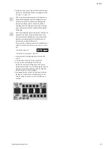
• Put the switch 2 on ON position (Fig. 4, item S).
The <7.0.0.0> menu is called up.
• Turn the encoder to activate or deactivate the
locking. The current state of the locking is repre-
sented with the following symbols:
Lock active: Parameters are locked,
the access to menus is allowed only
on reading.
Lock inactive: Parameters can be
changed, the access to menus is allo-
wed for setting.
• Return the switch 2 on OFF position (Fig. 4, item
S). The display returns to the status page.
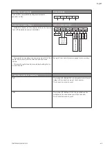
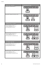
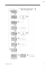
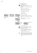
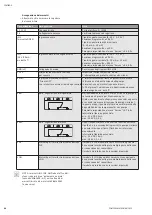
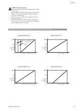
8.1.6 Configurations
NOTE : If the pump is delivered as separate part,
not integrated into a system we mounted, the
standard configuration mode is
« Speed control ».
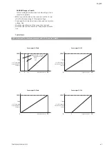
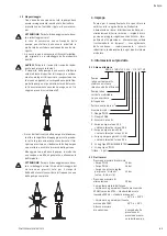
« Speed control » mode (Fig. 1, 2)
Setting of the frequency by hand or external
control.
• For the starting up, we recommend to set the
motor speed at 2400 RPM.
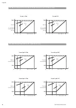
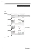
« Constant pressure » mode (Fig. 6, 7, 8)
Regulation with a pressure sensor and setting
point (internal or external).
• The addition of a pressure sensor (with tank;
sensor kit delivered as accessories) allows a
pressure regulation of the pump (with no water
in the tank, pressurize the tank to a pressure 0.3
bar less than the pressure regulation of the
pump).
• The accuracy of the sensor shall be ≤ 1% and it is
used between 30 % and 100 % of the measuring
scale range. The tank must have a useful volume
of 8L minimum.
• For the starting up, we recommend a pressure set
value at 60% of its maximum pressure.
« P.I.D. control » mode
Regulation with a sensor (temperature, flow...) by
P.I.D.control and setting point (internal or exter-
nal).
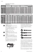
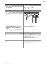
8.2 Preliminary rinsing
The hydraulic features of every pump is tested in
factory, some water may remain in them. It is
recommended for hygien purposes, to carry out a
rinsing of the pump before any using with
potable water supply.
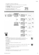
8.3 Filling - degassing
CAUTION!
Danger of material damage!
Never operate the pump dry, even briefly!
Pump in load (Fig. 2).
• Close the discharge valve (item 3).
• Open the venting plug (item 5), the suction valve
(item 2) and completely fill the pump.
• Close the venting plug only after water flows out
and complete aeration.
WARNING!
Danger of burn!
In hot water, a stream of water may escape from
the venting plug port.
• Take all required precautions as regards persons
and motor-converter.
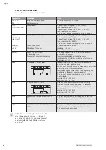
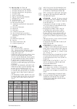
Pump in suction (Fig. 1, 5)
Two possible cases:
1st case
(Fig. 5.1)
• Close the discharge valve (Fig. 1, item 3), open
the suction valve (Fig. 1, item 2).
• Remove the venting plug (Fig. 1, item 5).
• Unscrew about 4 turns the bottom drain-priming
plug (Fig. 1, item 6) located on the pump casing.
• Put a funnel into the venting plug port and com-
pletely fill the pump and the suction pipe.
• After water flows out and total air exit, filling is
achieved.
• Screw the venting plug and the bottom drain-
priming plug back in.
2nd case
(Fig. 5.2)
• Filling can be made easier by fitting a vertical
pipe (Fig. 5, item 14) fitted with a Ø ½" stopcock
and a funnel, on the suction pipe of the pump.
NOTE: The length of the pipe must be at least 50
mm higher than the venting plug level.
• Close the discharge valve (Fig. 1, item 3), open
the suction valve (Fig. 1, item 2).
• Open the stopcock (Fig. 5, item 14) and the
venting device (Fig. 1, item 5).
• Unscrew about 4 turns the drain-priming plug
(Fig. 1, item 6).
• Completely fill the pump and the suction pipe
until water flows out of the venting plug (Fig. 1,
item 5).
• Close the stopcock (Fig. 5, item 14) (which can
be left in place), remove the pipe, close the
venting device (Fig. 1, item 5) and screw again
the drain-priming plug (Fig. 1, item 6).
CAUTION !
Risk of misuse!
Pump in load and in « Constant pressure » mode,
the detection at zero flow can not run.
• Set the non-return valve before the pressure
sensor (i.e. at pump suction if the sensor is
mounted on this one – Fig. 6).
POMPES SALMSON 06/2013
Summary of Contents for MULTI-VE Series
Page 2: ......
Page 3: ......
Page 5: ...5 11 7 6 1 13 3 2 7 100 mm Mini 200 mm Mini 100 mm Mini HA 2 BP Fig 1...
Page 6: ...8 9 12 5 11 2 3 2 7 7 4 4 6 13 10 ou or ou or 100 mm Mini HC Fig 2...
Page 8: ...Fig 4...
Page 9: ...2 14 1 Fig 5...
Page 10: ...10 17 16 ou or 15 Fig 6 10 ou or 17 15 16 Fig 7...
Page 11: ...17 16 15 Fig 8...
Page 12: ...19 18 Fig 9 Fig 10...
Page 13: ...Fig 11...


