


9
SALICRU
3. Presentation.
3.1.
Views.
3.1.1. Views of the equipment.
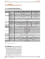
Figures 1 to 4 show the illustrations of the equipment according
to the case format and depending on the power of the model.
Nevertheless and due to the constant evolution of the product,
some discrepancies or small contradictions can arise. In front
of any doubt, the labelling of the equipment will always prevail.
Figures regarding its main features or specifications can
be checked in the nameplate of the equipment. Keep them
in mind for its installation.
1. LCD Back-Light.
2. Power «ON/OFF» Switch.
Fig. 1.
Front view from SOHO+ 400/600/800 VA.
1. Communication Port.
2. Modem/Phone Line Surge Protection.
3. AC Output.
4. AC Input.
5. Circuit breaker.
Fig. 2.
Rear view from SOHO+ 400/600/800 VA.
1. LCD Back-Light.
2. Power «ON/OFF» Switch.
Fig. 3.
Front view from SOHO+ 1000/1400/2000 VA.
SOHO+ 1000 VA
SOHO+ 1400/2000 VA
1. Communication Port.
2. Cooling Fan.
3. AC Output.
4. Modem/Phone Line Surge Protection.
5. AC Input.
6. Breaker.
Fig. 4.
Rear view from SOHO+ 1000/1400/2000 VA.
Summary of Contents for SPS SOHO+ series
Page 2: ......
Page 19: ...19 SALICRU...