14
SALICRU
5.1.4.1. Rack-type mounting in a 19” cabinet (SPS AdvAnCe R devices).
•
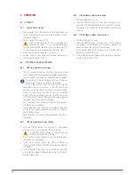
Proceed as follows (see fig. 7):
Using the supplied screws, fix the two adapter angles
for use as handles on each side of the UPS, respecting
its mounting orientation.
To install the device in a rack cabinet, it is necessary
to have internal lateral guides for use as supports. Al-
ternatively, and upon request, we can supply universal
slides for use as guides, for installation by the user.
Fig. 7.
SPS ADVANCE R mounting in a 19” cabinet.
mount the guides at the required height, ensuring cor-
rect tightening of the fixing screws and appropriate fit-
ting in the machining, according to each case.
Place the device onto the guides and insert it all the
way to the back.
depending on the device model and weight, and/or
whether it is installed in the upper or lower part of the
cabinet, it is recommended that two people carry out
the installation operations.
fix the UPS to the cabinet frame using the screws sup-
plied with the handles.
5.1.4.2. Preliminary considerations before connection.
•
Check that the information on the device’s nameplate is
that required for installation.
•
Thermal control of the Adv T models is carried out with the
passage of forced air from the front to the rear.
10 cm on the front surface and its rear side should be left
free of obstructions to facilitate the free circulation of air
for ventilation.
•
Protection board:
It will have a type-b differential circuit breaker and a short
circuit protection (C-curve circuit breaker) for the UPS’s
input line
As for size, they will be at least the current indicated on the
nameplate of the UPS.
•
only the rated current as indicated by the en-IeC 62040-1
safety standard is printed on the nameplate of the device.
for the calculation of the input current, the power factor and
the equipment's own performance have been considered.
overload conditions are considered a non-permanent and
exceptional working mode.
•
The cross section of the input line cables is determined by
the current indicated on the nameplate of each device, in
compliance with local and/or national Low-voltage electro-
technical Regulations.
•
If peripheral input and/or output elements, such as trans-
formers or autotransformers, are added to the UPS, the cur-
rents indicated on the nameplates of these elements must
be taken into consideration when determining appropriate
cross sections, in compliance with local and/or national
Low voltage electrotechnical Regulations.
•
when a device incorporates a galvanic isolation
transformer as an optional extra or installed inde-
pendently, either at the input, output or both, it must be
fitted with protection against indirect contact (differential
circuit breaker) at the output of each transformer, since, due
to its own insulation properties, it will prevent the tripping
of the protections placed on the primary of the isolation
transformer in case of electric shock on the secondary
(output of the isolation transformer).
•
we remind you that all the isolation transformers installed
or factory supplied, have the output neutral grounded
through a bridge between the neutral terminal and ground.
If the isolated output neutral is required, this bridge must
be removed, taking the precautions indicated in the respec-
tive local and/or national low voltage regulations.


