Salicru SLC ADAPT2 Series User Manual Download Page 30

30

SALICRU


ˆ

Connection to a three-phase bypass network:

Connect the R-S-T-N power supply cables to the bypass 

terminals, respecting the order of the phases and the 

neutral indicated in the labelling of the device and in 

this manual. If the phase order is not respected the de-

vice will not work.

It is essential to connect the input neutral.


ˆ

Connection to a single-phase bypass network:

Connect the R-N power supply cables to the bypass 

terminals, respecting the order of the phases and the 

neutral indicated in the labelling of the device and in 

this manual. Failure to observe the phase and neutral 

order will cause serious damage to the device.

Where there are discrepancies between the labelling and the 

instructions in this manual, labelling shall always prevail.

For systems in parallel, it will be necessary to repeat the 

connections that go from the panel to each device.


Frequency converter mode.

 With the frequency 

converter configuration activated, the cables of the 

static bypass line must not be connected. With 

this operation mode, all the functionalists of the static by-

pass are inhibited.

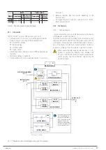
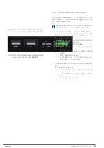
5.5.3.  Output connection, terminals.


As it is a device with protection against class I elec-

trical shock, it is essential to install the protective 

earth conductor to the terminal identified as 

. Connect 

this conductor before supplying voltage to the input termi-

nals.


Connect the output cables to the respective terminals ac-

cording to the configuration of the available equipment, 

taking into account the illustrations in 

  to  

 in terms of the 

connection points of the cables.


ˆ

Three-phase output connection:

Connect the loads to the U-V-W-N output terminals, 

re-

specting the order of the phases and the neutral 

indicated in the labelling of the equipment and in this 

manual. If the phase order is not respected the device 

will not work.

Where there are discrepancies between the labelling 

and the instructions in this manual, labelling shall al-

ways prevail.


ˆ

Single-phase output connection:

Connect the loads to the U-N output terminals, re-

specting the order of the phase and the neutral indi-

cated in the labelling of the device and in this manual. 

Failure to observe the phase and neutral order will 

cause serious damage to the device.

Where there are discrepancies between the labelling and the 

instructions in this manual, labelling shall always prevail.

For systems in parallel, it will be necessary to repeat the 

connections that go from the panel to each device.


Frequency converter mode.

 You can use the de-

vice with the frequency converter configuration, ac-

tivating this function through the control panel menus. For 

connection purposes, the order of connection of the phase 

or phase and neutral cables to the load or loads shall be 

respected.


With regard to the protection to be placed at the output of 

the protection board or manual bypass (optional), we rec-

ommend the distribution of the output power via at least 

four lines. Each of them will have a magneto thermal pro-

tection switch of adequate value. This type of output power 

distribution will ensure that a fault in any of the machines 

connected to the device that causes a short circuit does 

not affect more than the line that is faulty. The remaining 

connected loads will have continuity assured due to the 

tripping of the protection only in the line affected by the 

short circuit.

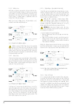
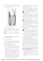
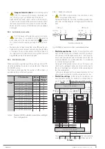
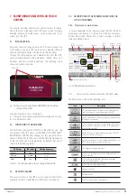
5.5.4.  Connection of the battery terminals of the device with 

those of the battery module.

The battery set can consist of 32, 36, 40 or 44 elements con-

nected in series, but always in even numbers since it is neces-

sary for the internal architecture of the device to have a central 

point or N neutral medium intake. At the same time, the back-

up time together with the power required to feed the loads de-

termines the Ah capacity of the accumulators.

Batteries connected in serial

N

BAT –

BAT +

N/2

N/2 +1

N–1

N

2

1

+               N

–               

Fig. 24. 

Typical connection of battery set.


As it is a device with protection against class I elec-

trical shock, it is essential to install the protective 

earth conductor to the terminal identified as 

. Connect 

this conductor before supplying voltage to the input termi-

nals.


The connection between the terminals of the cabinet or 

battery pack and the UPS will always be made through the 

supplied cable hose, respecting the polarity indicated in the 

labelling of each unit and the colour of the cables or their 

identification at the ends through heat shrink sleeve (red 

for positive “+”, blue for common “N” and black for nega-

tive “-”).

It is imperative to respect this rule and not to extend the 

hose supplied.


For extended back-up time in which more than one module 

or battery cabinets are supplied, the connection will always 

be in parallel between them and in turn with the device. 

Respect the rule indicated in the previous point for the con-

nection.


For 6-slot cabinets in parallel the connection of the bat-

teries with the UPS will not change, since each group of 

accumulators is connected directly with its UPS.

However, there is also another possibility, a set of batteries 

inside a cabinet or installed in a rack, and common to a UPS 

system with 6 slots in parallel.

Summary of Contents for SLC ADAPT2 Series

Page 1: ...SLC ADAPT2 UNINTERRUPTIBLE POWER SUPPLY USER MANUAL...

Page 2: ...ents 5 1 2 Storage 5 1 3 Unpacking 5 1 4 Transport to the site 5 2 LOCATION 5 2 1 Location of the ADAPT2 5 2 2 Room for the batteries 5 3 ENTRY FOR THE CONNECTION CABLES 5 4 PROTECTIVE DEVICES AND CRO...

Page 3: ...Map of screens accessible from the Main Screen 7 4 2 Measurements menu 7 4 3 UPS alarms menu 7 4 4 Status Ops menu 7 4 5 Rated values menu 7 4 6 Charts menu 7 4 7 Advanced menu 7 4 8 Other screens 7...

Page 4: ...we accept no liability for any errors or omissions that may exist The images included in this document are for illustrative purposes and may not exactly represent the parts of the device shown theref...

Page 5: ...rs from that shown in the figures in Chapter except when it differs in the number of mod ules connected in parallel and or the technical specifi cations are modified additional explanatory annexes wil...

Page 6: ...is a product for com mercial and industrial application in the second environ ment Installation restrictions or additional measures may be necessary to avoid disturbances It is not appropriate to use...

Page 7: ...ass Module Battery Isolator Switch Power modules Manual Bypass Isolator Switch Optional LCD Fig 1 Front views of the 24U cabinet with the door closed left and the door open with 2 and 4 modules instal...

Page 8: ...solator Switch Manual Bypass Isolator Switch Optional Communications interface See Bypass Module Fig 3 Front views of the 33U cabinet with the door closed above left and the door open with 2 4 and 6 m...

Page 9: ...Terminal block See Detail A page 7 External battery terminals Manual Bypass Terminals Optional Fig 4 Rear views of the 33U cabinet with protective cover removed for 2 4 and 6 modules installed SLC AD...

Page 10: ...Detail A page 7 Disconnector Manual Bypass Optional Manual Bypass Terminals Optional Communications interface See Bypass Module LCD Fig 5 Front views of the 42U cabinet with the door closed left with...

Page 11: ...rnal battery terminals Communications interface See Bypass Module Disconnector Manual Bypass Optional Manual Bypass Terminals Optional Fig 6 Front view left and rear view right of the 42U cabinet with...

Page 12: ...nal block See Detail B page 9 External battery terminals Communications interface See Bypass Module Disconnector Manual Bypass Optional Manual Bypass Terminals Optional Fig 7 Front view left and rear...

Page 13: ...x 15 kVA No 3 x 15 kVA Yes 3 x 15 kVA Yes 60 kVA 36 kVA 6 x 10 kVA No 6 x 10 kVA Yes 90 kVA 54 kVA 6 x 15 kVA No 6 x 15 kVA Yes Table 1 Total available power depending on the height of the cabinet an...

Page 14: ...14 SALICRU N Cable gland Battery terminals Fig 9 Rear view of battery cabinets Disconnector Fuses Fig 10 Front view of battery cabinets...

Page 15: ...ade in Spain in UPS and packaging for customs 100A Protection size 165 Last three digits of the battery code AB Letters of the battery family 36 Number of batteries in a single branch x Number of para...

Page 16: ...ut needing to shut down the hot swappable system all with the simple use of a screwdriver to remove or tighten the fixing screws of the module s Although all of the UPS modules incorporate a battery c...

Page 17: ...parate terminals for the PFC rectifier power supply and the static bypass However unless otherwise requested the termi nals of the phases of both blocks are connected in the factory by means of bridgi...

Page 18: ...he UPS is out of service When the UPS is operating in bypass mode over static bypass connected devices are not protected against power cuts or micro cuts overvoltages voltage and or frequency variatio...

Page 19: ...ormance point even when working with low loads This is achieved by activating one of two possible modes although each has a different purpose Normal Sleep mode The inverter of the modules is activated...

Page 20: ...han parts of the input signal cycle less than 15 ms for 50 Hz and 12 5 ms for 60 Hz 4 3 3 4 Manual Bypass status external or optional If the UPS requires intervention due to breakdown or for main tena...

Page 21: ...tery type For example for valve regulated lead acid batteries VRLA the maximum fast charge voltage should not exceed 2 4 V cell Float charging The float voltage can be adjusted for the type of batteri...

Page 22: ...g the device s manufacturing number and delivery note references It has not suffered any mishaps during transportation packaging and impact indicator in perfect condition Otherwise follow the protocol...

Page 23: ...od remove the corner protectors and the plastic sheath Only equipment in sub rack format is packed onto pallets Fig 21 Device unpacked by way of example 5 1 4 Transport to the site If the receiving ar...

Page 24: ...to have a good air circulation of the room The stability and ambient temperature of the room where the battery is located is an important factor that determines the capacity to store the energy durin...

Page 25: ...indicated in the tables and that are conditioning to determine the respective data provided although the installer will be responsible for defining the particularities of the installation cables cros...

Page 26: ...he effects that this may have on the loads connected to its output ac cording to their type and or tolerance to variations 5 4 2 Battery installation and maintenance Batteries are a source of energy s...

Page 27: ...be configured for 32 36 40 and 44 12V elements and is calibrated at the factory with the number of cells according to the battery set supplied or the number of items requested when the batteries are...

Page 28: ...f the UPS Consider the cross section of the cables and crimped termi nals at their ends in relation to the surface and size of the terminals to obtain optimum contact between them At the end of the wi...

Page 29: ...single terminal block common power supply for the rectifier and the static bypass line However when both functional blocks are powered through two independent lines it is essential to remove the bars...

Page 30: ...evice Frequency converter mode You can use the de vice with the frequency converter configuration ac tivating this function through the control panel menus For connection purposes the order of connect...

Page 31: ...ding to their configuration 5 5 6 1 Parallel bus connection The COM communications line constitutes a very low voltage safety circuit To preserve the quality it must be installed separately from other...

Page 32: ...xpansion board IS All connectors related with communications are grouped to gether on the interface panel and can be accessed from the Bypass module after removing the cover which covers them complete...

Page 33: ...is located behind the cover giving access to the communication connections located next to the monitoring panel with touch screen see To install the SNMP card 1 Remove the screws securing the access...

Page 34: ...Refer to to to identify parts of the device shows a manual bypass board for a parallel system of N units with a common AC line and with independent net works for the rectifier and bypass In both the...

Page 35: ...r ALARM They change in colour and flashing frequency Although both the colours and the flashing frequencies of the RGB LEDs can be programmed by default they are as shown in 6 3 OPERATIONS OF THE MANU...

Page 36: ...itch turn the manual bypass switch on the sub rack to Off and place its mechanical lock For safety it is necessary to block the switch me chanically otherwise there is a risk of unexpected operation o...

Page 37: ...on the icon in the Status Ops menu to enable the power module shut down function 2 Using the On Off button next to the LED indications on the front panel manually stop the power module Use an object...

Page 38: ...itution en tails the necessary programming of the same parameters as the original module This task must only be carried out by our T S S staff or the distributor Replacing one MBS with another without...

Page 39: ...UCH SCREEN 7 4 1 Start menu or main screen by way of example shows the main screen that the LCD moni toring panel can display It is basically divided into four areas System information Power flow Curr...

Page 40: ...rmation can be viewed on the Main Screen 1 Measured input frequency 2 Measured input voltages per phase 3 Measured output frequency 4 Measured output voltages per phase 5 Battery temperature 6 Ambient...

Page 41: ...41 SLC ADAPT 2 UNINTERRUPTIBLE POWER SUPPLY SYSTEM USER MANUAL...

Page 42: ...l in volts Three currents at the UPS Output measured per phase in Amperes Three power factors at the UPS Output per phase Measured UPS Output frequency in Hz Three UPS output load percentages one per...

Page 43: ...Rectifier Back Alarms Inverter Output power Info 0 0 0 0 0 0 0 0kW 0 0kVA 0 0kVA 0 0kVA 0 0kW 0 0 0 0 Measurements Alarms Status Ops Ratings Charts Advanced 0 1 4 PM S3 3 Power measurements at the mod...

Page 44: ...anced users Switch BYP Switch to Bypass mode Switch INV Switch to Inverter mode Extract Module Button to allow extraction of modules Unlock UPS Unlock button Boost Float Button to switch manually from...

Page 45: ...V cell 270 Volts End of Backup Voltage at a discharge current of 0 15 x C per cell in Volts Half bus EOD Voltage 0 15 x C 40 bat teries 2 half buses x 6 cells battery x 1 75 V cell 210 Volts End of Ba...

Page 46: ...Status Ops Ratings Advanced Charts User Start 0 1 4 PM S3 3 Screen brightness adjustment screen Slide the control with a finger or press or to increase or de crease the brightness of the touch sensiti...

Page 47: ...N bus connection fault in Inverter UPS 24 ALM_SYNC_PULSE_FAIL Fault in the low frequency synchronisation signal MODULE 25 ALM_BATTERY_VOLT_DETECT_FAIL Low battery UPS 26 ALM_OUTPUT_VOLT_FAIL_R Inverte...

Page 48: ...N_X_REDUNDANT Loss of Redundancy UPS 14 WRN_BATTERY_TEST_FAIL Battery Test results in Fail MODULE 15 WRN_BATTERY_MAINTENANCE_FAIL Discharge Test results in Fail MODULE 16 WRN_AMBIENT_OVER_TEMP Ambient...

Page 49: ...RY_MAINTENANCE_OK Discharge Test OK 18 EVN_MODULE_INSERTED Module inserted 19 EVN_MODULE_EXIT Module Extracted 20 EVN_MANUAL_TRANSFER_BYP Manual Transfer from Inverter to Bypass 21 EVN_ESC_MANUAL_BYPA...

Page 50: ...ion is automatic and requires no attention except in the excep tional circumstance of one of its protection fuses tripping Do not manipulate disconnector with backfeed protection fuses except when rep...

Page 51: ...9 1 2 Exclusions The company will not be bound by the warranty if the defect in the product is considered to not exist or to have been caused by improper use negligence inadequate installation and or...

Page 52: ...mperature C 20 70 UPS Recommended battery storage temperature C 0 25 20 C for optimum storage Table 15 Environmental characteristics 10 3 MECHANICAL CHARACTERISTICS Specifications of the cabinets Unit...

Page 53: ...Voltage ripple V floating 1 Power ripple C10 5 Quick charge voltage equalisation V cell VRLA 2 4 selectable between 2 30 2 45 Mode of charging to current and constant voltage End of discharge voltage...

Page 54: ...erload 110 permanently 150 during 1 min Transfer time ms 0 Manual bypass type Uninterrupted Rated current of neutral line A 1 7 In Frequency Hz 50 60 Sync Window Hz Rated frequency 2 selectable from 0...

Page 55: ...ns to the connection strip it is necessary to make changes through the password restricted screen exclusively reserved for our T S S or distributors The bridging strips for the different configuration...

Page 56: ...s Fig 44 Single phase input Single phase output separate supplies to Rectifier and Bypass 2 and 4 slots Terminal block in 2 slot and 4 slot UPSs Fig 45 Single phase input Three phase output separate s...

Page 57: ...Registering the device in the cloud There are two ways to register the device in the cloud using the portal and using a QR code 11 2 1 1 Nimbus portal 1 Go to https nimbus salicru com 2 To register t...

Page 58: ...ncise description to identify the product That way if you have registered other SALICRU devices you can use this field to easily differentiate between them The device s location and the corresponding...

Page 59: ...email in your inbox After you click on the link contained in the email you will be able to create a new password Click on Save to save changes 11 2 1 7 Adding the device 1 Once you have logged in see...

Page 60: ...pear and the new device will be added to your list of registered devices 11 2 2 General technical specifications In the Tab 6 below lists the technical specifications of the NIMBUS card Specifications...

Page 61: ...nt conductive layers and a special crystalline material in the middle liquid crystal which have the ability to orientate light as it passes through LED Light Emitting Diode a semiconductor device diod...

Page 62: ...62 SALICRU...

Page 63: ...63 SLC ADAPT 2 UNINTERRUPTIBLE POWER SUPPLY SYSTEM USER MANUAL...

Page 64: ...y salicru salicru_SA Product Range Uninterruptible Power Supplies UPS Stabilisers Step Down Light Dimmers Power Supplies Static Inverters Photovoltaic Inverters Voltage Stabilisers Information about o...

Reviews: