


29
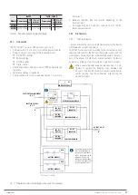
5.5.1. Connecting the device to the mains.
•
As it is a device with protection against class I elec-
trical shock, it is essential to install the protective
earth conductor to the terminal identified as
. Connect
this conductor before supplying voltage to the input termi-
nals.
•
In accordance with the safety standard EN-IEC 62040-1, in
devices without independent bypass line, the installation
must be equipped with an automatic backfeed protection
system, such as a contactor, which prevents the occurrence
voltage or hazardous energy on the UPS input line during a
mains failure.
The standard is applicable regardless of whether the power
supply is single-phase or three-phase, and for individual
units of sub-racks as well as for each of the UPS sub-racks
of a parallel system.
All values are calculated for a
maximum total cable
length of 30 m
between the distribution board, the device
and the loads.
•
There can be no derivation of the line from the Back-
feed protection to the UPS, since the safety standard
will not be complied with.
•
Warning labels shall be affixed to all primary power
switches installed in areas remote from the device to alert
electrical maintenance personnel of the presence of a UPS
in the circuit.
The label shall bear the following text or an equivalent:
Before working on the circuit.
•
Isolate the uninterruptible power supply system (UPS).
•
Check the voltage between all terminals, including the
protective earth.
Risk of UPS return voltage.
•
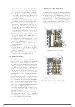
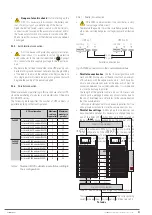
Connect the input cables to the respective terminals ac-
cording to the configuration of the available equipment,
taking into account the illustrations in
to
of ANNEX I in
terms of the connection points of the cables.
Connection to a three-phase input mains:
Connect the R-S-T-N power supply cables to the input
terminals,
respecting the order of the phases and
the neutral
indicated on the labelling of the equipment
and in this manual. If the phase order is not respected
the device will not work.
It is essential to connect the input neutral
Connection to a single-phase input mains:
Connect the R-N power cables to the input terminals,
respecting the order of the phases and the neutral indi-
cated on the labelling of the device and in this manual.
Failure to observe the phase and neutral order will
cause serious damage to the device.
Where there are discrepancies between the labelling and the
instructions in this manual, labelling shall always prevail.
For systems in parallel, it will be necessary to repeat the
connections that go from the panel to each device.
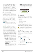
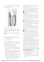
•
In general, the devices are supplied ready for pow-
ering through a single terminal block (common power
supply for the rectifier and the static bypass line).
However, when both functional blocks are powered through
two independent lines,
it is essential
to remove the bars
or strips that connect the terminals of the respective
phases and
leave the bar or connection strip installed
between the
two Neutral terminals
.
•
The input Neutral for the rectifier power supply and
the input Neutral for the bypass line power supply
must be the same. In any case,
remember
that within the
equipment, both neutrals will be connected through the bar
or strip that joins the two terminals
.
•
Frequency converter mode.
You can use the de-
vice with the frequency converter configuration, ac-
tivating this function through the control panel menus. For
connection purposes, the order of connection of the phase
or phase and neutral cables must be respected.
When a device operates as a frequency converter,
it
is essential
to remove the connection strips be-
tween the input terminals of the UPS and those of the inde-
pendent bypass line. This will prevent inappropriate
transfers of the input on the output in case of operating the
manual bypass switch (optional).
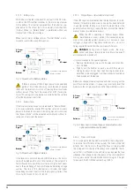
5.5.2. Independent static bypass line connection. In version
B only.
•
As it is a device with protection against class I elec-
trical shock, it is essential to install the protective
earth conductor to the terminal identified as
. Connect
this conductor before supplying voltage to the input termi-
nals.
•
In accordance with safety standard EN-IEC 62040-1, in
devices with a static bypass line, the installation must be
equipped with an automatic backfeed protection system,
such as a contactor, to prevent the presence of voltage
or hazardous power on the UPS input line during a mains
failure and another for the bypass line.
The standard is applicable regardless of whether the power
supply is single-phase or three-phase, and for individual
units as well as for each of the UPSs in a parallel system.
•
There can be no derivation of the line from the Back-
feed protection to the UPS, since the safety standard
will not be complied with.
•
Warning labels shall be affixed to all primary power
switches installed in areas remote from the device to alert
electrical maintenance personnel of the presence of a UPS
in the circuit.
The label shall bear the following text or an equivalent:
Before working on the circuit.
•
Isolate the uninterruptible power supply system (UPS).
•
Check the voltage between all terminals, including the
protective earth.
Risk of UPS return voltage.
•
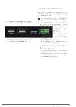
Connect the bypass input cables to the respective terminals
according to the configuration of the available equipment,
taking into account the illustrations in
to
in terms of the
connection points of the cables.
SLC ADAPT 2
- UNINTERRUPTIBLE POWER SUPPLY SYSTEM
-
USER MANUAL