


25
•
On request we can supply an external protection board or
manual bypass board for a single unit or a manual bypass
board for a parallel system.
You can also choose to manufacture one, taking into ac-
count the version and configuration of the available device
or system and the “Recommended installation” documen-
tation that can be downloaded from the website.
•
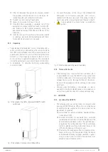
On the nameplate of the cabinet you can check all
the values referring to the main characteristics re-
lated to the equipment.
The cabinet has two nameplates. One that defines the
configuration of the unit supplied and one that identifies
the configuration of the highest power model that can be
installed, that is, supposing that it incorporates all of the
modules for which it has capacity. In all cases, the cross
sections of the cables and protections must be in accord-
ance with the data on the first one.
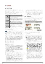
•
In the documentation downloaded from the website
or supplied with the CD-ROM or Pen Drive, the user
manual, the EK266*08 safety instructions and the informa-
tion on the "Recommended installation", technical data and
single-line diagrams on the connection of the system to the
installation, are also available.
These data are useful for determining the minimum protec-
tions and sections to be installed at the input and output of
the ADAPT2, taking into account their rated working voltage,
input-output configuration and the number of modules in-
stalled in parallel.
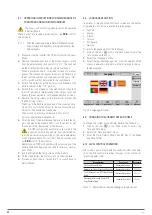
It is possible to opt for any of the two solutions re-
garding the size of the panel protections:
a.
Protections sizes according to the power installed in the
cabinet. Future expansions will require the ratings to be
updated to adjust the protection to the installation.
b.
Protections size considering maximum expandable
power or up to where future scaling extension is envis-
aged. This option is the most economically beneficial if
future expansions are envisaged.
It is recommended that the cable cross section of the
switchboard be suitable for option “
b.
”.
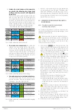
•
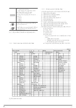
In order to determine the particular technical characteristics
of the system in the respective table of specifications, only
the number of modules working in parallel will be taken
into account, but not those that function in redundant.
Pay attention to the notes indicated in the tables and that
are conditioning to determine the respective data provided,
although the installer will be responsible for defining the
particularities of the installation (cables cross sections,
protections size, ...), since it is the person who has all the
information regarding the system's location environment.
All values given in the tables are calculated for a
max-
imum total cable length of 30 m
between the distribu-
tion board, the equipment and the loads.
For longer lengths correct the cross sections to avoid
voltage drops, respecting the regulations or standards
corresponding to the country.
The same documentation contains, for each configura-
tion, the information for N units in parallel (in 6-slot
cabinets), as well as the characteristics of “Backfeed
protection”.
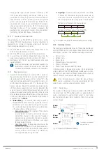
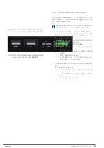
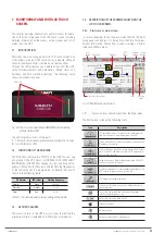
•
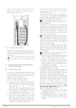
The 6-slot cabinets have two elliptical panel-entry holes in
the base of the cabinet (see
). Make the necessary cuts
that allow the passage of cables.
Fig. 23.
Cable entry on 6-slot cabinet.
On the base itself and between the two elliptical panel-entry
holes there is a metal plate that can be extracted and ma-
chined for the installation of cable glands or conical panel-
entry glands.
It is essential to fix the cables to the points provided,
as shown in
, so as not to obstruct the ventilation air
outlet.
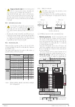
5.4. PROTECTIVE DEVICES AND CROSS-SECTIONS OF
THE CONNECTION CABLES.
5.4.1. Input, bypass and output.
•
The cabinets only include an external battery disconnector
that can be operated by the user, and a manual bypass
switch (optional) that is useful during preventative mainte-
nance or in case of device failure.
These are located at the front of the cabinet.
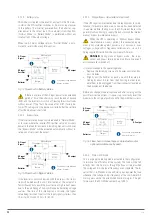
•
Protection or external manual bypass board:
It is necessary to have an external protection board pro-
vided with the mechanisms of input, output, and static
bypass (the latter only on models with independent
static bypass line).
In addition it is highly recommended to include a manual
bypass mechanism to facilitate preventive maintenance
or repair operations, so we will refer to it as a manual
bypass board instead of a protection board.
For cabinets in parallel, it is essential to have a manual
bypass board. The panel mechanisms must allow a
cabinet to be isolated from the set of systems in par-
allel in the event of any anomaly and to feed the loads
with the rest, either during preventive maintenance or
during the failure and repair of some of them.
SLC ADAPT 2
- UNINTERRUPTIBLE POWER SUPPLY SYSTEM
-
USER MANUAL