19
SALICRU
•
The DC Power-L can be supplied from the factory with con-
nection of positive to earth, negative to earth or float. On the
nameplate and terminal labelling, the type of connection is
identified by means of symbols ‘+’ or ‘–’ placed before the
value of the output voltage and the symbol for live pole is
indicated.
It is
very important
to ensure that the loads to be connected
to the device have the same type of connection as this one,
otherwise it would pose a risk to personnel and destroy the
system and associated devices.
By default and if not indicated otherwise, all devices have
floating output voltage.
•
It is recommended to use shielded cables for com-
munications, as well as the earth connection of the
screen through the terminal or strip.
7.4. Connection of the system to the
cabinet or battery bank.
•
This operation is only intended for the connection between
the battery terminals of a system and the respective ones
of the cabinet or cabinets, or battery bank, regardless of
whether the batteries are owned by the customer or supplied
with the device.
All of the instructions concerning the physical installation of
each of the elements inside the system or battery cabinet are
described in Section 7.1.
•
All of the protections or disconnectors of the system must be
in the ‘Off’ position and, in particular, that of the the batteries
of the device
(Q3)
and its counterpart
(Q8)
in the accumulator
cabinet, when it has an external battery bank.
Since the fuses of the disconnectors are supplied al-
ready installed to prevent them from being lost or mis-
laid, it is important to check that the disconnectors are open
(Off).
•
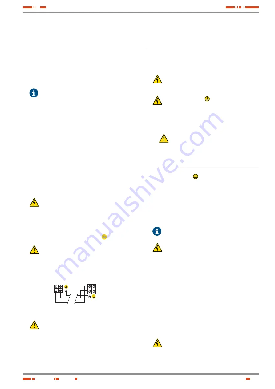
Connect the cable hose, usually supplied, between termi-
nals of the system and those of the battery cabinet or bank,
respecting the colour of the cables (red for (+), black for (–)
and green-yellow for the earth bonding
( )
) as well as the
polarity indicated on the label of the device (see Fig. 7).
•
In systems with more than one battery cabinet/bank,
the connection in parallel between them and the
system will be taken into account according to each particular
case. The battery connection diagram supplied with the doc-
umentation will always take precedence.
Battery terminals in
accumulator cabinet.
Battery terminals in
rectifier cabinet.
Fig. 7.
Connection of the system to a battery cabinet.
•
Do not start the system without having previously con-
nected the batteries to the device.
7.5. Connection to the main single-
phase or three-phase AC power
supply network.
•
All of the protections or disconnectors of the system must be
in the ‘Off’ position and, in particular, that of the the batteries
of the device
(Q3)
and its counterpart
(Q8)
in the accumulator
cabinet, when it has an external battery bank.
Since the fuses of the disconnectors are supplied al-
ready installed to prevent them from being lost or mis-
laid, it is important to check that the disconnectors are open
(Off).
•
The earth connection
( )
of the device must be con-
nected to the terminal or strip, making sure that this is
done before connecting the voltage to the input of the device.
•
Connect the power supply cables to the terminals indicated
for single-phase devices
F, N
or for three-phase systems
R,
S, T, N,
respecting the order of the phase or phases and the
neutral indicated on the labelling of the DC Power-L.
If the phase order is not respected, the three-
phase device will not work.
7.6. Connection of the loads to DC
output terminals.
•
The earth connection
( )
of the device must be connected
to the terminal or strip intended for that purpose, making sure
that this is done before connecting the voltage to the input of
the device.
•
The DC Power-L can be supplied from the factory with posi-
tive or negative connection referenced to earth, or float. On
the nameplate and terminal labelling, the type of connection
is identified by means of symbols ‘+’ or ‘–’ placed before the
value of the output voltage and the symbol for live pole is
indicated.
By default and if not indicated otherwise, all de-
vices are dispatched from the factory with floating
output voltage.
It is
very important
to ensure that the loads to be con-
nected to the device have the same type of connec-
tion as this one, otherwise it would pose a risk to personnel
and destroy the system and associated devices.
•
The type of output protection is predetermined and estab-
lished as follows:
For floating output, two-pole protection.
For output with positive referenced to earth, single-pole
protection in negative pole.
For output with negative referenced to earth, single-pole
protection in positive pole.
The type of output protection is also applicable to the battery
switch or protection and to any DC distribution protection.
•
All of the protections or disconnectors of the system must be
in the ‘Off’ position and, in particular, that of the batteries of
the device
(Q3)
and its counterpart
(Q8)
in the accumulator
cabinet, when it has an external battery bank.
Since the fuses of the disconnectors are supplied al-
ready installed to prevent them from being lost or mis-
laid, it is important to check that the disconnectors are open
(Off).
Summary of Contents for DC POWER-L Series
Page 2: ...2 USER MANUAL...
Page 31: ...31 SALICRU...


