26
Screen 5.9
Use this screen to set the minimum time the battery must remain
at float before allowing a battery test to be initiated.
Screen 5.10
Use to consult and modify the batteries’ float voltage compensa-
tion, according to the temperature.
Screen 5.11
Use to consult and modify the batteries fast charge voltage com-
pensation, according to the temperature.
Screen 5.12
Sets the maximum and minimum temperature threshold for the
battery temperature compensation.
Screen 5.13
Enable or disable fast charging and periodic battery charging.
Screen 5.14
Enable or disable exceptional battery charging.
Screen 5.15
Use this screen to consult and modify the batteries’ fast charging
voltage.
Screen 5.16
Use to consult and modify the batteries’ maximum fast charging
time.
Screen 5.17
Use to adjust the battery tail current for return to float.
Screen 5.18
Use to consult and modify the batteries’ fast manual charging
time.
Screen 5.19
Use to consult and modify the batteries’ periodic charging time.
Screen 5.20
Use to specify the interval of days between periodic loads.
Screen 5.21
Use this screen to consult and modify the batteries’ exceptional
charging voltage.
Screen 5.22
Use to consult and modify the batteries’ maximum exceptional
charging time.
Screen 5.23
Use this screen to consult and modify the batteries’ maximum
charging interval, between exceptional battery charging regimes.
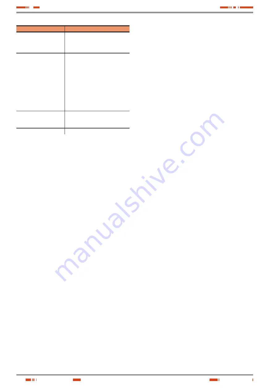
RELAY
ASSOCIATED ALARMS
RELE 1: (AC Input failure)
Input overvoltage.
Input undervoltage.
Input switch open.
AC input failure.
Phase rotation error.
RELE 2: (EMERGENCY fault)
Output overvoltage.
Output undervoltage.
High battery voltage.
Low battery voltage.
Battery fuse blown.
Rectifier fuse blown.
Input switch open.
Output switch open.
Reducer overheating (ventilation fault).
Battery disconnected.
Battery failure.
Rectifier overheating (SCR sink)
Battery overheating.
File system fault.
Charger fault.
RELE 3: (NON-EMERGENCY
fault)
Battery leakage current (+)
Battery leakage current (-)
Fault Battery temperature sensor.
Surge protector triggered.
RELE 4: (End of backup)
End of battery backup.
Table 8.
Table of activation conditions for external indication relays.
9.3.6. ‘Battery Settings’ menu.
To access this menu from the home screen, press the forward
key
(
)
five times. Use key
(
)
to access the screens of the
different sub-menus and move freely from one to the other by
means of keys
(
)
and
(
)
.
Screen 5.1
This is the gateway to the Battery Settings menu. If you enter the
correct ‘Password’ on Screen 7.1, you can see and modify the
parameters of the batteries in the adjacent screens. Otherwise,
none of the screens in this menu will be displayed.
Screen 5.2
Use this screen to change the capacity of the installed battery
and the maximum charging current.
Screen 5.3
Use this screen to change the value of the float voltage.
Screen 5.4
Use this screen to consult and modify low battery voltage alarms.
Screen 5.5
Use to consult and modify the battery unit’s low voltage cut-off.
Screen 5.6
Use this screen to change the value of the battery unit’s high
voltage alarm.
Screen 5.7
Use to consult and modify the battery unit’s high voltage cut-off.
Screen 5.8
Use this screen to modify the value of the battery high voltage
alarm.
USER MANUAL
Summary of Contents for DC POWER-L Series
Page 2: ...2 USER MANUAL...
Page 31: ...31 SALICRU...


