background image

47

Smarty 3X VE / Smarty 3X VE 3.0

www.salda.lt

2.0

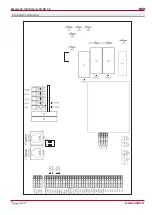
PRV CONTROL

System Mode

Normal

Calculating main PID

Main PID

30 < Main PID < 50

0 < Main PID < 30

50 < Main PID < 100

Bypass Control

Heating

Cooling

StandBy

Alarm

Cool down electric

heating elements

Cool down electric

heating elements

Toutside < Troom

Heat reccuperation

Calculating main PID value between 

Tset and Tsupply to determinate 

what type of ventilation we need

ByPass-CLOSE

ByPass-OPEN

ByPass-OPEN

Toutside < Troom

+

-

+

-

ByPass-OPEN

Cold reccuperation

Toutside < -3

and

Texhaust<ExhaustSet

Indicating Alarm

+

-

PreHeater-Off

PID Texhaust; ExhaustTest

END

Ventilation with Temperature

maintenance by cooling

Ventilation with Temperature

maintenance by heating

Ventilation with Temperature

maintenance by controling 

ByPass

Trying to maintenance Ex-

haustTset

Summary of Contents for Smarty 3X VE Series

Page 1: ...Subject to technical modification AHU WITH HEAT RECOVERY Smarty 3X VER Smarty 3X VEL Smarty 3X VER 3 0 Smarty 3X VEL 3 0 User s and service technical manual ...

Page 2: ...nter mode setting 24 10 Comfortable supply air temperature 25 11 Night cooling 25 12 Heat cool recovery 25 13 Fast button stand by mode 26 14 Filter timer 28 15 Boost fireplace function 29 16 Bypass damper and its control 30 Connection of the unit to electric network 30 Recommendations for installation of functional modules opera tional control measurement 31 CO2 concentration according to Pettenk...

Page 3: ...es includes 1 Siphon 1 pcs 2 Key 1pcs 3 Anti vibration mounts 4 pcs 4 Anti vibration rubber 2 pcs 5 Mounting bracket 1 pcs 200003025238 IV PV KE PE M 0 084 kW 0 92 A 230 50 V Hz 1 0 085 kW 0 93 A 230 50 V Hz 1 kW A 0 V Hz 0 kW A 0 V Hz 0 0 005 kW 0 021 A 24 50 V Hz 0 17 kW 1 87 A IP 34 TOTAL gu072489 2014 03 www salda lt 1 3 4 5 2 6 200003025238 IV PV KE PE M 0 084 kW 0 92 A 230 50 V Hz 1 0 085 kW...

Page 4: ...779 2013 Extract panel M5 WxHxD 435 x 175 x 25 mm Supply panel F7 WxHxD 435 x 175 x 25 mm Outdoor exploitation temperature 5 C to 40 C Not suitable for swimming pools saunas and other similar facilities All units are packed in the factory to withstand regular conditions of transportation The unit can be lifted using metal rods Pic 1 Rod diameter 35 40 mm Upon unpacking check the unit for any damag...

Page 5: ...ronment Do not use the unit if external connections are broken or damaged If there are any defects stop operating the unit and replace the damaged parts immediately That can be performed only by qualified electrician Do not use water or another liquid to clean electrical parts or connections If you notice water on electrical parts or connections stop operating the unit Unit is designed to operate ...

Page 6: ...n for the life of the motor Detach fan from the unit Impeller should be specially checked for buil up material or dirt which may cause an imbalance Excessive imbalance can lead to accelerated wear on motor bearings and vibration Clean impeller and inside housing with mild detergent water and damp soft cloth Do not use high pressure cleaner abrasives sharp instruments or caustic solvents that may s...

Page 7: ...7 Smarty 3X VE Smarty 3X VE 3 0 www salda lt Smarty 3X VEL Smarty 3X VEL 3 0 ...

Page 8: ...d to have been damaged in transit a claim should be made against carrier as we assume no responsibility for such damage 3 This warranty does not apply 3 1 when transportation storage installation and maintenance instructions of the unit are violated 3 2 when the equipment is improperly maintained inadequate maintenance 3 3 when the equipment without our knowledge and permission has been upgraded o...

Page 9: ...current kW A 0 3 1 3 control input ON OFF Pre heater EKA NIS phase voltage 1 230 power current kW A 1 0 4 3 control input 0 10 V Smarty 3X VER Smarty 3X VER 3 0 Smarty 3X VEL Smarty 3X VEL 3 0 Smarty 3X VER Smarty 3X VER 3 0 Smarty 3X VEL Smarty 3X VEL 3 0 Exhaust air Smarty 3X VER Smarty 3X VER 3 0 Smarty 3X VEL Smarty 3X VEL 3 0 Extract air Smarty 3X VER Smarty 3X VER 3 0 Smarty 3X VEL Smarty 3X...

Page 10: ...y 3X VE Smarty 3X VE 3 0 www salda lt 750 500 162 113 113 372 160 150 6 150 6 233 8 113 113 372 160 150 6 150 6 233 8 750 500 162 598 943 Smarty 3X VER Smarty 3X VER 3 0 598 943 Smarty 3X VEL Smarty 3X VEL 3 0 ...

Page 11: ...level of noise caused by the fans is admissible The installation is recommended at the distance of 400 mm from the nearest wall If it is not possible the installation of the unit is recommended on the wall of the room where the level of noise is not important Also vibrations can be transmitted through the floor If possible additionally insulate the floor to suppress the noise Pipes are connected t...

Page 12: ...n control panel technical manual Stretch the connection cable which is included into standard package between the control panel and control box The cable of the control panel can t be stretched together with power cables Due to insufficient control panel cable stretching disturbance between the unit and control panel can be caused Connect all necessary including additionally ordered accessories to...

Page 13: ...etwork connection place RS485_1 Control panel connection place PC Personal computer MBGateway Net module Flex Control panel Stouch Control panel M2 Fresh air damper actuator Recommended to use with return spring M3 Exhaust air damper actuator WSG Supply and exhaust air grilles PE EKA NIS Electric pre heater KE EKA Electric heater AVA M5 Water cooler There is only actuator control signal from autom...

Page 14: ...damper ZAKP0027 TF230 Spring return actuator for damper ZAKP0063 MPL Panel filter set GKOFILSMARTY3 FLEX Remote control panel PRGPU015 Stouch Remote control panel PRGPU051 S KCO2 CO2 sensor ZAKKT0049 EKA 160 0 3 1f Electric heater PSIEKA075 EKA NIS 160 1 0 1f Electric preheater PSIEKANIS03 WSG Supply and exhaust air grill GGRWSG0126_509 Net module GAUMBGATEWAY001 MB Gateway ...

Page 15: ... the temperature reaches 3 C anti frost protection stars to work Pre heater EKA NIS for anti frost protection has to be ordered additionally The pre heater has overheat protection protection limiting the tempera ture which starts at 50 C and manual which starts at 100 C Other information Adjusting and setting of the function Configuration is impossible with Stouch Default configuration for unit s ...

Page 16: ...rheating or accidental oxygen burning The electrical supply air heater is controlled according to the PID controller on the basis of the on off control principle When the unit is switched off the heating elements are cooled This period may be changed by the remote control Flex only Other information The heater EKA is ordered individually The heater has the automatic protection against overheating ...

Page 17: ... fan operation mode can be used where prompt indoor air changes are required at the increase of air pollution e g if the number of people in a room quickly increases The fan speed in this case is increased up to the set maximum boost value The maximum speed value and operation time may be configured by remote controls Modes of each fan speed can be configured individually i e different values can ...

Page 18: ...nu Additional Service password Vent Control off Where the CO2 transmitter is used by Stouch remote control In the remote control Flex select Menu Additional Service password Vent Control The parameter CO2 value is changed to OFF The system installer shall design the transmitter power supply and protection circuits Power supply parameters are indicated in the technical passport of the transmitter T...

Page 19: ...Extra SAF Ctrl SAF low Where Stouch remote control is used all settings made by Flex remote control become inactive All settings of this function must be made by Stouch remote control Time can be configured Elements Command Action Indication B4 B5 B6 L2 Intense ventilation function boost switch on switch off Hold B5 for 2 seconds L2 flashes The segment display shows the remaining time in seconds t...

Page 20: ...ms supply and extract air it is necessary to use two pressure transmitters 1141 They are ordered individually Pressure transmitters are used only when connected by Flex remote control The use of forced ventilation boost by a digital input To activate this function a button or motion sensor PIR can be used 4 5 connection of an external button or PIR sensor To reduce CO2 concentration at the premise...

Page 21: ...rding its proper connection Connection of a functional node to a ventilation unit To use this function the short circuiter must be removed from terminals 5 and 6 its installation is standard 5 6 PIR building alarm system door lock input NC the unit is on NO the unit is off The unit automation has the additional indication designed i e where light indication is connected it is possible to identify ...

Page 22: ... Supply air actuator M3 phase L1 steady signal 20 Supply air actuator M3 phase L1 control variable signal Actuator supply voltage 230V 50Hz When the water cooler is used we recommend to connect the spring return actuator This will ensure the water cooler protection in case of the unit supply voltage loss In this case M2 actuator is switched on as follows 15 Supply air actuator M2 neutral N 17 Supp...

Page 23: ...FF permit can be active by means of the unit shut down function Where the supply air temperature drops below 16 5 C the unit control automation records it as the minimum permissible supply air temperature and the message critical supply temperature is shown on the remote control By activating this function it is possible to choose how long low temperature may be supplied before the message is show...

Page 24: ... time meter is activated in the service menu Menu additional sevice FMisc Ftimer Function adjustment setting By FLEX remote control Menu Extra filters Set Timer service hours until the information message for filter replacement are set designed time till the filter replacement is 2 160 service Other information hours ReSet Timer resetting the meter Curr Timer current number of service hours Menu A...

Page 25: ...in the unit s technical decal on the unit casing The unit must be connected to the voltage plug socket of the grounded power network in compliance with the effective requirements The unit must be earthed according to the rules on installing electrical equipment The start up and operation of the unearthed ventilation unit is prohibited It is prohibited to use extension wires cables and power networ...

Page 26: ...stretching The standard length of the unit s power cable is 2 5 m long from the unit casing The supply air sensor SS must be installed as far from the unit as the sensor cable enables or to the first branching turn of the air transportation system It is recommended to install supply air sensors as far from the heater cooler as possible in order to receive more accurate temperature measurement resu...

Page 27: ... Fig 4 5 When the unit control automation must be extended from the automation compartment the limiting automation extension screw must be unscrewed and two connectors of the automation must be disconnected If external units are connected to X16 they must be also disconnected prior to extending automation The unit must be connected to the power supply through the current leakage relay 30 mA Upon t...

Page 28: ... installed in the extract air duct Tool for drilling holes are required for its installation CO 2 concentration ppm 3000 Effect on an individual 2500 2000 Reduced concentration drowsi ness headache etc 1500 1000 Pettenkofer limit Pettenkofer limit Disturbs 500 Pleasant 0 0 1 2 3 4 Duration of the presence in the room in hours Closed windows Controlled ventilation Šviežias lauko oras ...

Page 29: ...tation is stopped if the device has rotor heat exchanger In the remote controller temperatures the set and the measured are displayed as degrees Celsius C Room air temperature can be adjusted not only according to the supplied air temperature sensor but also according to the extracted air sensor see FLEX panel description II 6 5 3 for details on selecting this feature When control algorithm of the...

Page 30: ... of the FLEX description If water supply air heater is used and after HVAC unit is switched on fans are switched on after 20 seconds During this period water valve actuator is being opened to allow water heater to reach the optimum temperature Two pressure converters should be used to control both fans while maintaining constant pressure at the system Also CO2 extract air converter can be connecte...

Page 31: ...mperature sensor for supply air TJK 10K TE exhaust air damper actuator TJK 10K DTJ100 1 temp and humidity sensor for extract air PV supply air fan EC IV extract air fan EC FA fire alarm input B1 units door micro switch Trans mitter transmitter air quolity P Dx cooler protection differential pressure switch PIR motion sensor S1 rotor heat exchanger speed sensor tik Smarty 3R R rotor heater exchange...

Page 32: ... System alarm 1 2W max 4 5 6 10 9 X16 4 24 1 2W max System on 11 12 COM FAN 25 24 23 24V DC 24 intput 0 10V DC 25 GND Transmitter 1 24 VDC P 23 X29 X25 N L 3 1 P DX Cooling A 0 10 COM 14 11 G M5 24VAC 3 position Y2 Y1 VAL VAL VAL X33 3 X33 4 X33 5 3 1 2 X16 1 24VDC Y1 Control OPEN AC 24 V Y2 Control CLOSE AC 24 V G System potential AC 24 V X35 2 X35 1 X33 13 X33 14 X33 18 X33 12 X33 17 X33 25 X33 ...

Page 33: ... System alarm 1 2W max 4 5 6 10 9 X16 4 24 1 2W max System on 11 12 COM FAN 25 24 23 24V DC 24 intput 0 10V DC 25 GND Transmitter 1 24 VDC P 23 X29 X25 N L 3 1 P DX Cooling A 0 10 COM 14 11 G M5 24VAC 3 position Y2 Y1 VAL VAL VAL X33 3 X33 4 X33 5 3 1 2 X16 1 24VDC Y1 Control OPEN AC 24 V Y2 Control CLOSE AC 24 V G System potential AC 24 V X35 2 X35 1 X33 13 X33 14 X33 18 X33 12 X33 17 X33 25 X33 ...

Page 34: ...X5 3 2 NO 1 COM 6 7 8 L X31 X33 15 X33 16 COM A 0 10 X41 1 X41 2 X39 2 X39 1 X38 1 X38 2 X40 3 X40 2 X40 1 X34 8 X34 7 X34 6 X34 5 X34 4 X34 3 X34 2 X34 1 X33 26 X33 25 X33 17 X33 12 X33 18 X33 14 X33 13 X35 1 X35 2 X33 5 X33 4 X33 3 VAL VAL VAL L N X25 X29 X33 11 X33 10 X33 9 X33 2 X33 1 X32 3 X32 2 X32 4 X32 1 RG1 COM T OUT RS485_1 N L X8 COM X33 13 X10 EXT EXT AC N X35 5 X35 4 X35 3 X33 21 X33 ...

Page 35: ...X5 3 2 NO 1 COM 6 7 8 L X31 X33 15 X33 16 COM A 0 10 X41 1 X41 2 X39 2 X39 1 X38 1 X38 2 X40 3 X40 2 X40 1 X34 8 X34 7 X34 6 X34 5 X34 4 X34 3 X34 2 X34 1 X33 26 X33 25 X33 17 X33 12 X33 18 X33 14 X33 13 X35 1 X35 2 X33 5 X33 4 X33 3 VAL VAL VAL L N X25 X29 X33 11 X33 10 X33 9 X33 2 X33 1 X32 3 X32 2 X32 4 X32 1 RG1 COM T OUT RS485_1 N L X8 COM X33 13 X10 EXT EXT AC N X35 5 X35 4 X35 3 X33 21 X33 ...

Page 36: ... applicable safety and functional requirements diameters etc earthing and protection systems are properly installed condition of all seals and sealing surfaces is proper The recuperator can be connected to the BMS network by using the ModBus protocol The device can be controlled using FLEX panel and BMS network simultaneously the device will work based on the latest changes of settings As set in t...

Page 37: ...air temperature set 0 30 17 RH_value 04h_Read_Input 13 1 DTJ 100 humidity sensor value 0 99 18 Motor1 04h_Read_Input 15 1 Motor1 fan speed value 0 3 19 Motor2 04h_Read_Input 16 1 Motor2 fan speed value 0 3 Temperature sensor value real format 3 3E38 3 3E38 example 0h 0C 7FFFh 3276 7C 8000h 3276 8 FFFFh 0 1C 20 Tlimit 04h_Read_Input 0 1 Supply air temperature value Real value 10 21 Texhaust 04h_Rea...

Page 38: ...r temperature limit day T is exceeded for the working unit and when temperature drops below Night T and the room temperature stays above Room T after switching the unit off 8 1 Day T 15 40 C maximum outdoor air temperature 8 2 Night T 0 15 C minimum outdoor air temperature 8 3 Room T 10 30 C indoor air temperature 8 4 Exercise 0 5 h Period for blowing measuring If the setting is 0 outdoor air sens...

Page 39: ...upply fan speed deceleration On allowed Off forbidden 15 3 Bypp Rot On Off on activation of anti frost protection On possible to open the bypass valve o to stop the rotor Off impossible to open bypass valve or stop the rotor 15 4 PassiveTC Off 16 5 C alarm report supplying low temperature air according to time set in 15 5 15 5 Excercise Off 1 12h how much time it is possible to supply low temperat...

Page 40: ...evel is exceeded the information message High CO2 level is displayed at the initial screen and the speed of fans is increased based on the amount at which allowable level is exceeded 5 In case of any fault of the CO2 converter menu Emergency overview shows message CO2 sensor Check if CO2 converter is properly connected only current input 1 Connect 0 10V control signal wire of the supply air pressu...

Page 41: ...s selected Bypass 0 10 Not used Cooling X16 4 X16 8 NO contact closed non voltage X16 1 X16 3 Activated by remote control V LED4 atidaroma X16 2 X16 3 Deactivated by remote control LED5 uždaroma Heating X16 30 X16 31 Supply air electrical heater Relay K6 LED13 Rot Bypass Damper opened heat exchanger closed LED6 atidaroma LED7 uždaroma Fan Run System On X16 11 ir X16 12 FanFail System Alarm X16 9 X...

Page 42: ...ire input A1 A1 Fire alarm activation Extract humidity X40 Extract air humidity sensor readings Supply air temp X39 Supply air temperature sensor failure Extract air temp X38 Extract air temperature sensor readings Outdoor air temp Extract air temperature sensor readings Exhaust air temp Outdoor temperature sensor readings Water temperature Exhaust air temperature sensor readings Extract CO2 Not u...

Page 43: ...s Seasons Exit Switch season Exit 3 days mean v Calendar Summer Winter Settings Exit Outdor air temp 0 C Summer 4MM 1DD Winter 11MM 1DD PI Kp 10 Ki 8 RoomPI Kp 100 Ki 10 HeatPI Kp 30 Ki 10 ChilPI Kp 10 Ki 10 PreHeatPI Kp 40 Ki 10 NightCtrl Day T 26 ºС Night T 16 ºС Room T 17 ºС Exercise 3 h Wheat W_crit 10 ºС W_stop 5 ºС Pump_stop 10 min Exercise 10 h Act Heater E_On OFF Exch B_DMP VentUnit RHEC ...

Page 44: ...Timer On AX 1 FansOn On AF AF detect Toutside FanReduct Off Bypp Rot Off PassiveTC Off Exercise AF 1 OutDoorTemp 1 RotorPWM 20 DefrStpTime 30 PassiveTemp 3 CONF1 3dayRH mean 30 3dayRHCurr 54 3dayOUTCurr 10 St Sp time 0 CONF2 DIBTmenu On 0 0 1 0 2 0 3 0 Filters SetTimer 2160 h ReSetTimer reset Curr Timer 2 h V2 4 programe coefficients Program SMARTY 3XVE V2 4 0k Extra Modbus MBAddress 1 Parity None...

Page 45: ...st EAF 1 SAF Ctrl SAF Low 0 3 SAF Midd 0 6 SAF High 1 EAF Ctrl EAF Low 0 3 EAF Midd 0 6 EAF High 1 SERVICE PI Kp 10 Ki 8 RoomPI Kp 100 Ki 10 HeatPI Kp 30 Ki 10 Byp RotPI Kp 10 Ki 10 ChilPI Kp 10 Ki 10 PreHeatPI Kp 40 Ki 10 NightCtrl Day T 26 o C Night T 16 o C Room T 17 o C Exercise 3 h Wheat W_crit 10 o C W_stop 5 o C Pump_stop 10 min Exercise 10 h Act Heater E_0_10 Exch B_DMP VentUnit RHEC FanTy...

Page 46: ... SAF High 100 VentCtrl SAF Percent EAF Percent CO2 Off Misc RC_NC Off F Timer On AX 0 FansOn On AF AF detect Klingb FanReduct On Bypp Rot On PassiveTC Off Exercise AF 1 RotorPWM 20 DefrStpTime 30 PassiveTemp 3 CONF1 3dayRH mean 30 3dayRHCurr 55 3dayOUTCurr 10 St Sp time 0 CONF2 DIBTmenu Off 0 0 1 0 2 0 3 0 Filters SetTimer 2160 h ReSetTimer reset Curr Timer 0 h ...

Page 47: ... reccuperation Calculating main PID value between Tset and Tsupply to determinate what type of ventilation we need ByPass CLOSE ByPass OPEN ByPass OPEN Toutside Troom ByPass OPEN Cold reccuperation Toutside 3 and Texhaust ExhaustSet Indicating Alarm PreHeater Off PID Texhaust ExhaustTest END Ventilation with Temperature maintenance by cooling Ventilation with Temperature maintenance by heating Ven...

Page 48: ...48 Smarty 3X VE Smarty 3X VE 3 0 www salda lt ...

Page 49: ... 50Hz delay of 3 minutes after stopping fans and heaters O 3A 100 X35 5 EXT L damper motor ON OFF 230V 50Hz O 3A 100 X3 RS485_2 ModBus I O X4 RS485_1 Remote controller FLEX I O X32 1 LOW Electrical heater guard from overheat ing I X32 3 HIGH BOOST increase the flow of air I X32 4 COM COM X33 1 TIMER Stop DI X33 2 COM COM M5 Water cooler valve actuator X33 3 VAL Cooling valve opening PWM 24v 50hz A...

Page 50: ...mitter DTJ100 1 DTJ100 1 Relative humidity transmitter has a built in NTC10K temperature sensor TA ß 3250 3300K Relative humidity transmitter supply voltage 5VDC Used current not higher than 5 mA Output analogue V DC Measurement limits 20 95 RH Accuracy 5 Safety class IP20 Dimensions IxPxA 63x38x15 mm Voltage V and relative humidity RH dependence 0 6V 20 RH 0 9V 30 RH 1 2V 40 RH 1 5V 50 RH 1 8V 60...

Page 51: ...ahr Filter replacement Замена фильтров Filter Ersatz Every 3 4 months Каждые 3 4 месяцев Alle 3 4 Monate NOTE The purchaser is required to fill in the Product maintenance table ПРИМЕЧАНИЕ Покупатель обязан заполнить Таблицу обслуживание продукта HINWEIS Der Käufer ist verpflichtet zu füllen Wartungstabelle des Produktes 2 At least Не менее Mindestens 2 Look at the product label Смотреть на этикетк...

Page 52: ...52 Smarty 3X VE Smarty 3X VE 3 0 www salda lt ...

Reviews: