4
[ lt ]
[ ru ]
[ en ]
[ de ]
RIS 700_1200_1900_2200 HE/HW EKO 3.0
I recuperatori di calore sono unità di ventilazio-
ne per il ricambio e la filtrazione dell’aria. Me-
diante lo scambiatore di calore l’energia termi-
ca contenuta nell’aria espulsa viene recuperata
e ceduta all’aria immessa. Sono costituiti da:
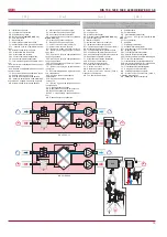
• Scambiatore di calore a piastre con rendi-
mento termico fino al 90%.
• By-pass automatico con valvola motorizzata
integrata.
• Batteria elettrica integrata, tipo di comando:
0-10V
(solo RIS HE EKO 3.0)
.
• Ventilatori EC ad alta efficienza e silenzio-
sità.
• Basso assorbimento elettrico: SFP (Specific
Fan Power) calcolato secondo EN13779
• Interruttore di sicurezza integrato EN 60204-
1:2006.
• 50 mm di isolamento acustico e termico
dell’involucro.
• Controllo automatico integrato, connessione
„Plug and Play“.
•Filtri paini M5/F7.
• Il dispositivo non è predisposto per l’uso
all’aria aperta
• Il dispositivo è dotato di sensori della tem-
peratura sull’aria immessa e sull’aria esterna.
• La versione standard prevede la logica di
controllo di tipo PRV 2.5.
• In opzione può essere previsto una logica di
controllo SIEMENS o Regin.
Il dispositivo non è adatto per l’utilizzo
in piscine, saune e altri locali simili, dove
l’umidità dell’aria estratta supera il 60% RH.
Recuperatore di calore non può essere uti-
lizzato come un riscaldatore dell’aria.
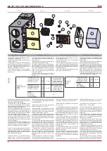
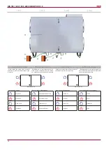
La fornitura standard include (senza accessori
opzionali):
1) dispositivo di ventilazione;
2) sifone – 2 pezzi;
3) maniglia avvitabile, chiudibile a chiave – 1
pezzo;
4) maniglia avvitabile – 1 pezzo.
5) Sensore temperatura aria immessa (TJ) 1
pz. (con batteria elettrica)
6) Kit antigelo per AVS (con batteria ad acqua)
L’imballo di tutte le unità garantisce l’integrità
del prodotto in condizioni normali di trasporto.
Dopo aver tolto l’unità dall’imballaggio, con-
trollare che non sia stata danneggiata durante
il trasporto. È assolutamente vietato montare
unità danneggiate!!!
L’imballaggio è solo un mezzo di protezione!
Caricando e scaricando le unità, usare mezzi
di sollevamento appropriati per evitare danni
e lesioni. Non sollevare mai le unità per mez-
zo dei cavi di alimentazione, per le scatole di
connessione, flange di aspirazione o di espul-
sione. Evitare urti o forti sollecitazioni al corpo
dell’unità.
Conservare le unità in un locale asciutto in
cui l’umidità relativa non deve superare il 70%
(a una temperatura di +20°C), e la temperatu-
ra media deve essere mantenuta tra i +5°C e
+30°C. Immagazzinare le unità in luoghi asciutti
ed al riparo dall’acqua e dallo sporco.
Le unità devono essere movimentate median-
te un carrello elevatore.
È sconsigliato lo stoccaggio per un periodo
superiore ad un anno. In caso di stoccaggio
per un periodo superiore ad un anno, prima del
montaggio controllare se i cuscinetti dei ventila-
tori e dei motori girano facilmente (far girare la
ventola con una mano), verificare l’integrità del
isolamento del circuito elettrico, controllare che
non vi siano segni di umidità.
Attenzione! La pellicola protettiva è desti-
nata a proteggere il prodotto durante la tra-
sportazione. Si raccomanda di rimuovere la
pellicola protettiva dopo la trasportazione,
altrimenti sul prodotto possono appartire le
tracce di ossidazione.
Все оборудование упаковано так, чтобы вы-
держало нормальные условия перевозки.
После распаковки убедитесь в отсутствии
повреждений при транспортировке. Уста-
новка поврежденных устройств запрещена!
Упаковка является только средством за-
щиты!
С целью избегания убытков и травм при раз-
грузке и складировании устройств пользуй-
тесь соответствующим подъемным оборудо-
ванием. Не поднимайте устройства за кабе-
ли питания, коробки подключения, фланцы
забора или удаления воздуха. Избегайте со-
трясений и ударных перегрузок. Устройства
храните в сухом помещении, где относитель-
ная влажность воздуха не превышает 70 проц.
(при +20ºС), а средняя температура окружа-
ющей среды составляет от +5ºC до +30ºС.
Место складирования должно быть защище-
но от грязи и воды.
Устройства на место их складирования или
установки доставляются подъемниками.
Не советуется складировать устройства
дольше одного года. При более длительном
хранении перед установкой необходимо убе-
диться в легкости хода подшипников венти-
ляторов и двигателей (повернуть крыльчатку
рукой), в отсутствии повреждений изоляции
электроцепи и конденсации влаги.
Внимание! Защитная плёнка предназначе-
на для защиты агрегата во время транспор-
тировки. После транспортировки рекомен-
дуется удалить защитную плёнку, иначе на
агрегате могут появиться следы оксидации
All units are packed in the factory to withstand
regular conditions of transportation.
Upon unpacking, check the unit for any dam-
ages caused during transportation. It is forbidden
to install damaged units!!!
The package is only for protection purpose!
While unloading and storing the units, use
suitable lifting equipment to avoid damages and
injuries. Do not lift units by holding on power
supply cables, connection boxes, air intake or
discharge flanges. Avoid hits and shock over-
loads. Before installation units must be stored
in a dry room with the relative air humidity not
exceeding 70% (at +20°C) and with the average
ambient temperature ranging b5°C and
+30°C. The place of storage must be protected
against dirt and water.
The units must be transported to the storage or
installation site using forklifts.
The storage is not recommended for a period
longer than one year. In case of storage longer
than one year, before the installation it is neces-
sary to verify whether the bearings of fans and
motor rotate easily (turn the impeller by hand)
and if the electric circuit insulation is not dam-
aged or the moisture is accumulated.
Attention! Protective film is intended to protect
the product during shipping. It is recommended
to remove the protective film after the shipping,
otherwise the product may get signs of oxidation
Alle Geräte sind werksseitig so verpackt,
dass sie den normalen Transportbedingungen
standhalten können.
Nach Auspacken des Gerätes überprüfen Sie,
ob es beim Transport nicht beschädigt wurde.
Beschädigte Geräte dürfen nicht montiert
werden!!!
Die Verpackung ist nur eine Schutzmaßnahme!
Beim Ausladen und Lagern der Geräte verwen-
den Sie geeignete Hebezeuge, um Schäden
und Verletzungen zu vermeiden. Heben Sie die
Geräte nicht an Netzkabeln, Anschlusskästen,
Zu- und Abluftstutzen. Vermeiden Sie Stöße und
Schläge. Lagern Sie die Geräte in einem trocke-
nen Raum, wo die relative Luftfeuchte höchstens
70% (bei +20°C) beträgt und die durchschnittli-
che Umgebungstemperatur zw5°C und
+30°C liegt. Der Lagerort muss vor Schmutz und
Wasser geschützt sein.
An den Lager- bzw. Montageort werden die
Geräte mit Hebezeugen transportiert.
Eine Lagerung länger als ein Jahr ist nicht
empfehlenswert. Bei einer Lagerung länger
als ein Jahr ist vor der Montage unbedingt zu
prüfen, ob die Ventilator- und Motorlager leicht-
gängig sind (Flügelrad mit der Hand drehen),
ob die Isolierung des elektrischen Stromkreises
nicht beschädigt ist und sich keine Feuchtigkeit
angesammelt hat.
Achtung! Schutzfolie schützt das Produkt nur
während des Transports. Es wird empfohlen,
die Schutzfolie nach dem Erhalt der Ware zu
entfernen, sonst kann das Produkt Anzeichen
von Oxidation erhalten.
Рекуператоры – это вентиляционные устрой-
ства, которые очищают, согревают и подают
свежий воздух. Устройства отбирают тепло
из вытяжного воздуха и передают его при-
точному.
Пластинчатый теплообменник, тепловая эф-
фективность которого – до 90 проц.
Интегрированные моторизованные заслонки
приточного и вытяжного воздуха.
Есть возможность подключить обходной кла-
пон (“By-pass”)
Интегрированный электрический нагрева-
тель, тип управления: 0-10V
(только RIS
HE EKO 3.0).
Производительные и тихо работающие ЕС
вентиляторы.
Низкий уровень SFP (Specific Fan Power)
EN13779.
Интегрированный переключатель безопас-
ного отключения EN 60204-1:2006.
Акустическая и тепловая 50 мм изоляция
наружных стенок.
Интегрированная автоматика управления,
подключение “Plug and Play”.
Панельные фильтры M5/F7.
Агрегат можно инсталлировать снаружи по-
ставляя крышу.
В комплекте датчики: приточного, вытяжного
воздуха, наружной температуры и влажности.
Стандартно поставляется с контроллером
автоматики PRV 2.5.
Возможность поставки с контроллером ав-
томатики SIEMENS или
Regin
.
Не приспособлены работе в помещени
-
ях (бассейн, баня...) где влажность возду
-
ха привышает 60%.
Рекуператор не может применяться как
нагреватель воздуха.
В стандартную упаковку (кроме дополни-
тельно заказываемых приложений) входят:
1) вентиляторное устройство;
2) сифон – 2 ед.;
3) прикручиваемая, запираемая ручка – 1
ед.;
4) прикручиваемая ручка – 1 ед.
5) Датчик температуры приточного воздуха
(TJ)1 шт (когда электрический нагреватель)
6) Комплект защиты от замерзания для AVS
(
только RIS HE EKO 3.0
)
AHUs are air ventilation devices that clean,
heat and supply fresh air. Units take heat from
exhausted air and transmit it to supply air.
Plate heat exchanger with temperature ef-
ficiency up to 90 %.
Integrated fresh and extracted air motorized
dampers.
There’s possibility to connect motorized
bypass damper;
Integrated electrical heater, Control type: 0-10V
(just RIS HE EKO 3.0).
Efficient and silent EC fans.
Low SFP (Specific Fan Power) level EN13779.
Integrated safety cut-off switch EN 60204-
1:2006.
Acoustic and thermal 50mm insulation of
external walls.
Integrated control automation, Plug and Play
connection.
Panel filters M5/F7.
AHU is ready for outdoors operation with the
accessories, i.e. roofing.
Intake and out-take air temperature sensors
and out-take air humidity sensor are installed
in the AHU.
As standard, supplied with Ewith automatic
controller PRV 2.5.
Optionally, can be supplied with automatic
controller SIEMENS or
Regin.
The device is not suitable for use in
swimming pools, saunas and other similar
premises, where the extracted air humidity
exceeds 60% RH.
The unit can not be used as an air heater.
Standard package (without optional acces-
sories) includes:
1) Ventilation unit;
2) Siphon – 2pcs;
3) Screwable lockable handle – 1pcs;
4) Screwable, handle – 1pcs.
5) Supply air temp. sensor (TJ)- 1pcs (for
electric heater)
6) Frost Protection Kit for AVS (
just RIS HE
EKO 3.0
)
WRG-Ventilatoren sind Lüftungsgeräte, die
reinigen, erwärmen und liefern frische Luft. Die
Geräte nehmen die Wärme von der Abluft und
übergibt sie der Luft, die geliefert wird.
Plattenwärmeaustauscher, dessen Tempera-
turleistung bis 90 % beträgt.
Integrierte motorisierte Klappen für frische
Luft und Abluft.
Es besteht Möglichkeit eine angetriebene
Bypassklappe anzuschließen.
Integrierter elektrischer Wärmer, Steue-
rungstyp: 0-10V
(nur RIS HE EKO 3.0).
Leistungsfähige und leise EC-Ventilatoren.
Niedriges SFP-Niveau (Specific Fan Power)
laut EN 13779.
Integrierter Abtrennschalter laut EN 60204-
1:2006.
Lärm- und Wärmedämmung der 50 mm-
Außenwände.
Integrierte Steuerautomatik, Plug and Play-
Anschluss.
Plattenfilter M5/F7.
Nur in Kombination mit Dach für Außenaufstel-
lung geeignet (Dach ist nicht im Lieferumfang
erhalten).
Im Gerät sind Zu-, Ab- und Außenluftfühler
sowie Abluftfeuchtefühler eingebaut.
PRV 2.5 Automatik-Regler gehört zum seriellen
Lieferumfang.
Es gibt Möglichkeit, mit einem Automatik-Regler
von SIEMENS oder
Regin
zu liefern.
Nicht geeignet für Schwimmhallen, Saunas
und andere Räume, wo Abluftfeuchte größer
als RH 60% ist.
Das Lüftungsgerät darf für Heizungszwe-
cke nicht verwendet werden.
Zur Standardverpackung (ohne Zubehör, das
zusätzlich bestellt wird) gehören:
1) Lüftungsgerät;
2) Siphon: 2 Stck.;
3) Verschließbarer Anschraubgriff: 1 Stck.;
4) Anschraubgriff: 1 Stck.
5) Zulufttemperaturfühler (TJ): 1 Stck. (wenn
mit elektrischer Wärmer);
6) AVS Frostschutz Kit (
nur RIS HE EKO 3.0
)


