


18
| EN
EIOM v2018.04
General:
If rotor does not rotate, check if:
• All cable connections (is any) are connected;
• Rotor motor is properly connected;
• Power supply voltage matches voltage indicated on the rotor motor plate;
• Thermal protection of the motor is activated (if any). When thermal protection is activated, contact becomes open (NO).
After starting the device, inspect:
• Rotor rotation direction. It has to match to the direction of indicated sticker (if any);
• Operation of the rotation sensor (if any);
Inductive rotation sensor
Single phase and three phase rotor (w/o control) can be equipped with inductive rotation sensor.
Rotation sensor can be used to identify if the rotor belt is broken or some other problems occurs.
Periodically perform the following checks to ensure stable operation of the sensor:
Check for mounting position, dislocation, looseness, or distortion;
Check for loose wiring and connections, improper contacts, and line breakage;
Check for attachment or accumulation of metal powder or dust;
Check for proper lighting of indicators (for models with a set indicator.)
Never disassemble or repair the Sensor.
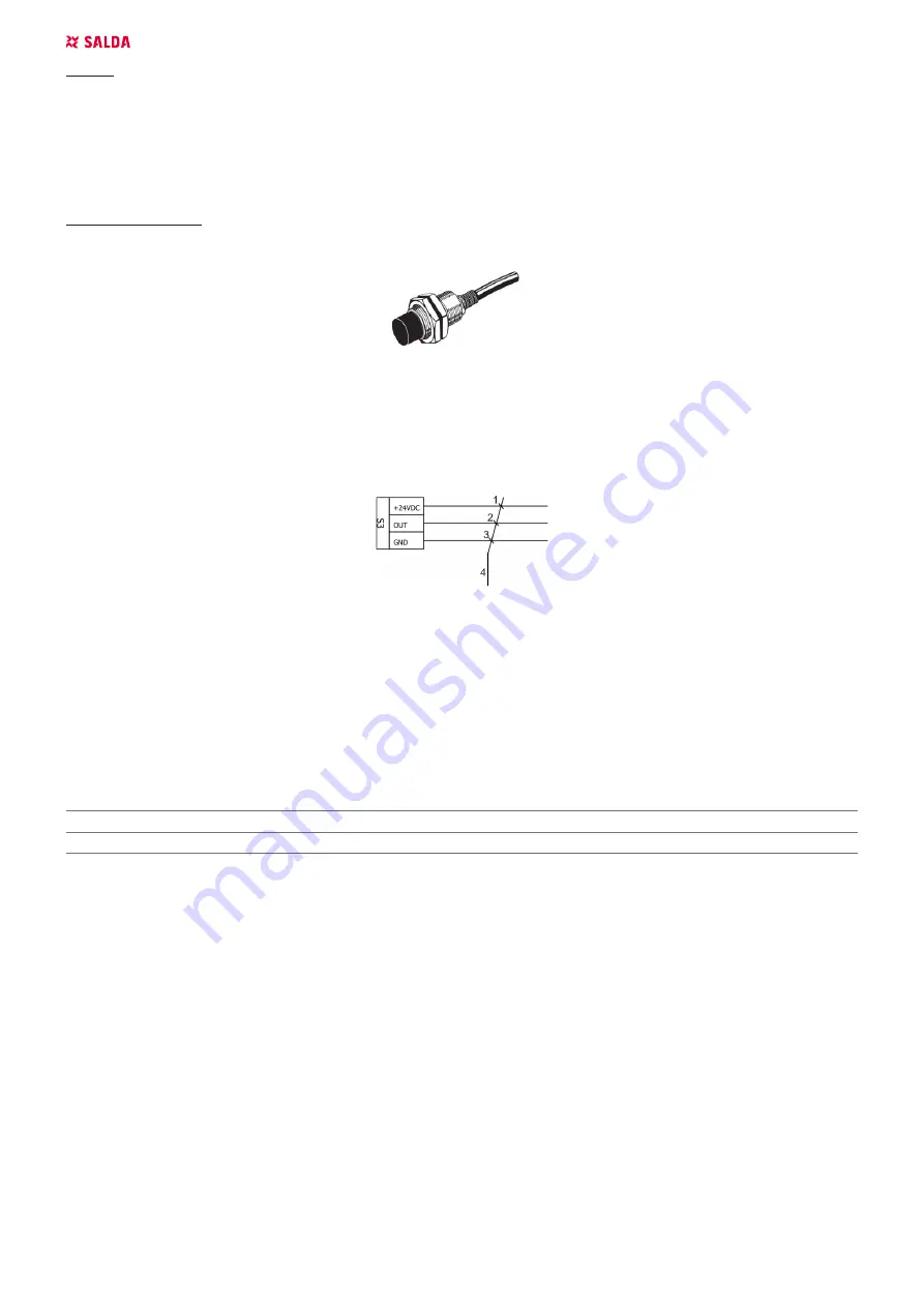
Figure 5.2.2.3– Inductive rotor sensor electrical wiring connection scheme
(1) – Brown; (2) – Black; (3) – Blue; (4) – Inductive rotor sensor cable;
5.2.3 STEPPING MOTOR WITH CONTROLLER
Step motor and controller type depends on the size of the unit:
Stepmotor controllers are OJ-DRHX series, EMX-R-..E or Varimax25;
Recommended cable cross-sectional area (mm
2
) for connecting step motor controller:
CABLE CONDUCTOR CROSS-SECTIONAL AREA, mm
2
PURPOSE
1.5
Motor power supply cable
0.5
Motor thermal cut-out cable
OJ-DRHX series
The DRHX series covers the range from 2Nm to 14Nm with both Modbus and analogue control.
The DRHX is equipped with a software that monitors the rotation of the rotor, which means that no physical/optical rotor guard is required.


