Safeaid TS350 Installation Setup Manual Download Page 6

SAFE-AID TS350 WIRED WIND SPEED METER MANUAL - VERSION 1


Page 6


MOUNTING


THE


ANEMO


4403


ANEMOMETER


TOOLS REQUIRED: 
 

1 x Welding Machine – Qualified welder to do welding 
1 x Hacksaw 
2 x 17mm Spanners 


PROCEDURE: 
 

1.  The  anemometer  head  unit  will  need  to  be  mounted  at  the  furthest  point  possible 

ensuring that the “wind vanes” are ABOVE the highest obstructive point i.e. on mobile 
cranes the unit should be mounted on the tip section above the level of the top of the 
boom so that even when the boom is at its highest point, the wind speed meter head 
is still above the boom head. 

2.  Find a suitable place to mount the anemometer. The mounting pole must be cut to the 

correct length, we recommend as short as possible to eliminate the possibility of the 
unit getting damaged or knocked off. The unit should be positioned correctly and have 
complete freedom of movement when swinging. The anemometer has a green nylon 
bush & washer where the pole slides through, this is fastened by using two M10 Nylock 
nuts & washers on either side of the spacer using the two 17mm spanners. Ensure the 
following: 

a. 

DO NOT

 tighten the nuts together too tightly as the anemometer will not be able 

to swing freely & self-level with the movement of the boom 

b.  Ensure  that  the  threaded  bar  is  flush  (inline)  with  the  inner  nut  so  that  the 

threaded bar does not touch or interfere with the cable i.e. if the threaded bar 
protrudes from the nut it will damage the cable. 

3.


Once  a  suitable  mounting  place  has  been  identified,  weld  the  mounting  foot  to  the 
crane’s boom. The anemometer is isolated and the bracket may be welded while the 
wind speed meter is attached to the pole. If the anemometer has been removed from 
the pole refit the anemometer as in point #2 above.
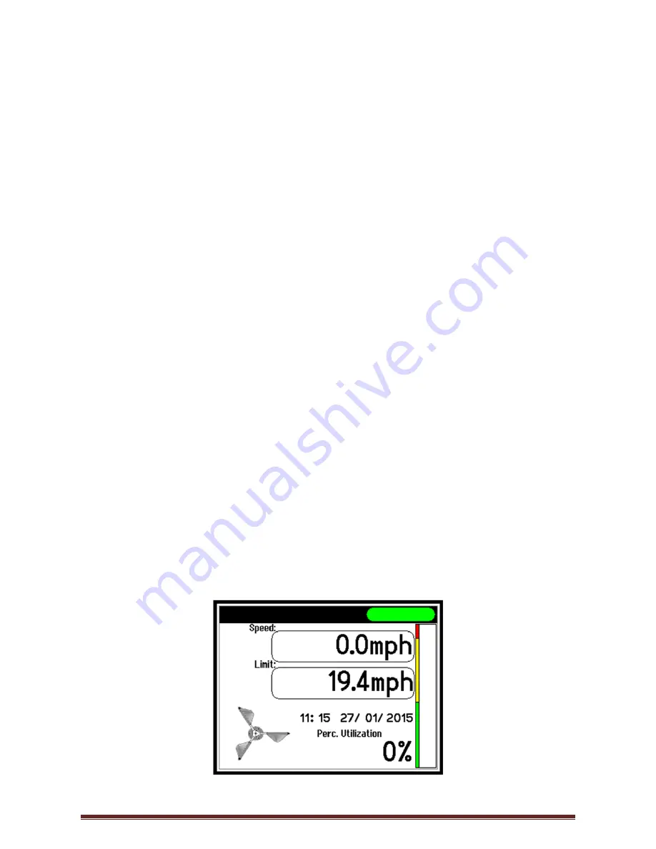
 

SYSTEM


USE


The Safe-Aid TS350 unit is designed with ease of operation in mind.   


Figure 1 

Summary of Contents for TS350

Page 1: ...E OF PROPER USAGE CANNOT BE OVERSTRESSED ALL INFORMATION IN THIS MANUAL SHOULD BE READ AND UNDERSTOOD BEFORE ANY ATTEMPT IS MADE TO OPERATE THE MACHINE SINCE THE MANUFACTURER HAS NO DIRECT CONTROL OVE...

Page 2: ...7 WIND SPEED LIMIT UNIT SETUP 9 SYSTEM SETUP TESTING 10 SETTINGS MENU 10 SET DATE TIME 11 CONTINUOUS LOGGING 11 RELOAD FIRMWARE 12 TEST MENU 13 SYSTEM INFORMATION 13 TS350 TESTS 14 TOUCH SCREEN CALIB...

Page 3: ...sition is best by turning the brackets to the desired position and then locking the universal bracket by turning the wing knob clockwise until the ball type bracket does not have any free movement 2 R...

Page 4: ...nnector on the main board To remove the back plate completely carefully unclip the connector from its receptacle 5 The USB is connected to the main board by brown blue white black wires terminated wit...

Page 5: ...ly Open Contact TOOLS REQUIRED 1 x 2 5mm Hex Head Allen key 1 x 2mm Flat Head Screwdriver PROCEDURE Connection can be done to both outputs intermediate and upper or individually as required 1 Open the...

Page 6: ...ned correctly and have complete freedom of movement when swinging The anemometer has a green nylon bush washer where the pole slides through this is fastened by using two M10 Nylock nuts washers on ei...

Page 7: ...te set of internal system diagnostics to make sure all inputs and outputs are working correctly Figure 2 The TS350 system goes into the working screen once all the relevant checks have been completed...

Page 8: ...ercentage utilisation bar graph will turn yellow Intermediate Windspeed will be displayed below the Limit block The display buzzer will sound intermittently Top robot type indication light on the top...

Page 9: ...equired units by pressing Wind Speed Units Wind Speed Units will now be highlighted blue and by pressing the select button the units will change Each time the Select button is pressed the units will c...

Page 10: ...password ______ ______ ______ ______ followed by the Enter key Contact your authorized distributor or email the factory for password access The Settings Test Menu screen will now be displayed Figure 1...

Page 11: ...igure 14 CONTINUOUS LOGGING For any logging of data to take place a USB flash drive memory stick must be inserted into the TS350 display unit i e the USB symbol is displayed in the top left corner The...

Page 12: ...s Logging Disabled Highlight Continuous Logging Press Select Select No Figure 15 RELOAD FIRMWARE These are advanced options and should only be done by or under the supervision of an authorized factory...

Page 13: ...f TS350 wind speed meter System Information TS350 Tests View Variables Test Inputs Test Outputs SYSTEM INFORMATION This screen Figure 21 displays the following information Display Serial no The last f...

Page 14: ...Test Inputs to view the digital inputs on the TS350 display board Figure 23 The box next to the relevant input will as follows Input present green block e g Input 1 No Input clear block e g Input 2 3...

Page 15: ...n has been entered by accident and touch calibration is not necessary press the Exit button without pushing anywhere else on the screen to continue with normal start up procedures If the touch screen...

Page 16: ...Figure 28 click Next to continue to the Installation Folder screen Figure 29 The application will automatically create a folder Elec Mech Windspeed Logger or select Change to select a different folder...

Page 17: ...fety co za BASICS OF THE PC LOGGING SOFTWARE ccWINDSPEEDLOG All the data stored on the USB flash drive can be downloaded and stored directly from the USB flash drive onto the PC using the ccWindSpeedL...

Page 18: ...SAFE AID TS350 WIRED WIND SPEED METER MANUAL VERSION 1 Page 18 Open the ccWindSpeedLog shortcut on the PC desktop Figure 34 Figure 34...

Page 19: ...ayed Figure 35 Figure 35 Enter the TS350 display serial number and click Add Click on the Unit Description box Figure 36 Figure 36 Type a customised description of the machine the TS350 is installed i...

Page 20: ...USB flash drive to the PC manually to allow the data to be managed The following process will run through the download of the files from the USB flash drive Figure 39 Once the USB flash drive has bee...

Page 21: ...ding the data files into the data base o Delete DataFile on Read this saves the data into the data base and deletes the file from the USB flash drive o Backup DataFile on Read this saves the data into...

Page 22: ...vant heading to reorder sort the downloaded files from low to high and vice versa Select the button Figure 42 and the select the options as laid out below o Report Date Range From date to date select...

Page 23: ...nit Register Date Time Date time that actual event occurred as per the TS350 Display Units real time clock Limit Data o The limit value at the time of event o The value for continuous logging o The va...

Page 24: ...leted will be displayed Figure 45 Click the button If all the events from a download have been deleted the download will be deleted Figure 46 Figure 46 Click the button Once complete click the button...

Page 25: ...SAFE AID TS350 WIRED WIND SPEED METER MANUAL VERSION 1 Page 25 Figure 47 Select the required database file mdb Click the button to use the selected data base...

Reviews: