


Operation and maintenance
Release: 2.8
Safco Systems S.r.l.
Via Isonzo 17/B – 20090 Cesano Boscone – Milan Italy
Tel. +39 024504433 Fax +39 024504321 E-mail:[email protected]
Web site: www.safcosys.com
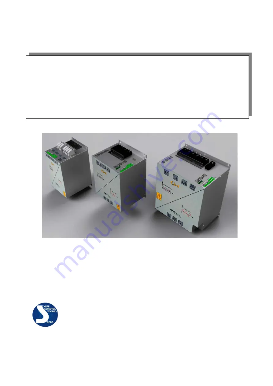
Control for resistance welding
Inverter technology
Models CS-I 150A CS-I 300A CS-I 450A CS-I 600A
(Square-wave transformers for DC)


