ADDITIONAL COMPONENTS REQUIRED
*Electric Motor:
10S-12S – 400-650Kv
Maximum diameter 64mm,
Maximum height 64mm, pinion shaft diameter 6mm
*Speed controller:
minimum 80A to be safe
*Batteries: 10-12S 3300-4000mAh
*1 flybarless 3 axis control unit
*Radio power system, if not integrated with the ESC
*3 cyclic servos
*1 tail rotor servo
*6 channel radio control system on 2.4 GHz
(See configuration examples on page 28)
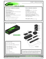
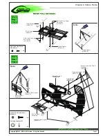
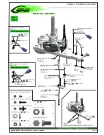
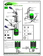
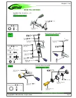
The assembly process is described in the following chapters of
this manual. Each phase begins with a green frame which gives
the box, the bag with screws (and miscellaneous items), and the
foam tray with the components required for the phase.
TOOLS, LUBRICANTS, ADHESIVES
*Generic pliers
*Hexagonal driver, size 1.5,2,2.5,3,4mm
*4mm T-Wrench
*5.5mm Socket wrench (for M3 nuts)
*8mm Hex fork wrench (for M5 nuts)
*Medium threadlocker (eg. Loctite 243)
*Strong retaining compound (eg. Loctite 648)
*Spray lubricant (eg. Try-Flow Oil)
*Synthetic grease (eg. Tri-Flow Synthetic Grease)
*Cyanoacrylate adhesive
*Pitch Gauge (for set-up)
*Soldering equipment (for motor wiring)
Inside the main box:
Box 2: Canopy, Blade Holder.
Box 3: Boom, Blades, Tail blades, Carbon rod.
Box 4: Mechanical parts in 4 trays:
Tray 1: Main rotor
Tray 2: Carbon frame and tail rotor
Tray 3: Transmission
Tray 4: Main structure
Box 5: Bags
Box 6: Carbon parts
Box 7: Combo Kit (optional)
Inside the main box there are:
Copyright@2012 - SAB Heli Division - All rights reserved
Page 3
Chapter 3, Components and Box

