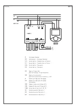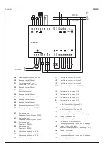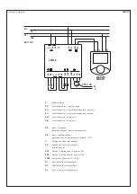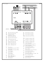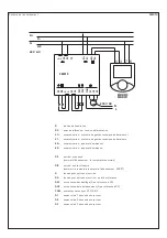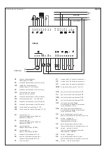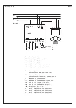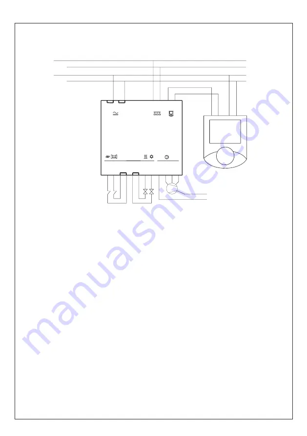
Schematic diagram
FM 010
G
Supply voltage
G0
Reference point – supply voltage
K1+
Communication – central building control
K1 –
Communication – central building control system –
K2+
Communication – room unit +
K2–
Communication – room unit –
DI1
Input – presence
(switches setback ⁄ normal temperature)
DI2
Input – window contact
(switches normal temperature ⁄ setback – OFF)
G
Voltage for inputs and outputs
G0
Voltage for inputs and outputs –
reference point
DO1
Output – heating valve (G, against G0)
DO2
Output – cooling valve (G, against G0)
COM
Common contact for Q1, Q2, Q3
Q1
Fan coil convector relay step 1
Q2
Fan coil convector relay step 2
Q3
Fan coil convector relay step 3
G
G0
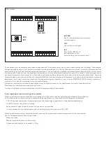
FM010
DI2
DI1
G
G
G0
G0
DO2
DO1
COM
Q3
Q2
Q1
N
L
6
7
4 3
K+
K-
MBR010
MBR011
24 V AC
230 V AC
G
TE
G0
G0
G
K1-
K1+
K2-
K2+
Summary of Contents for THERMASREG FM Series
Page 30: ...ZVEI VDE EMV VDE r...
Page 32: ...THERMASREG FM D G F r...


