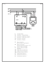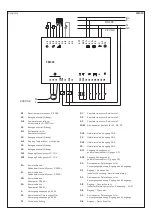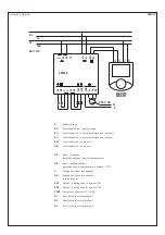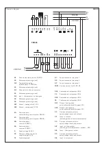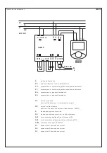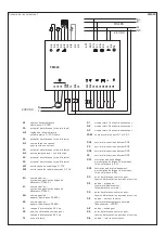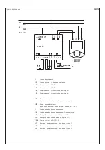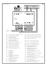
Schematic diagram
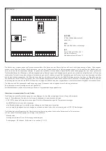
FM 020
AI1
Room temperature sensor, Pt1000
G0
Reference potential (ground)
AI2
Temperature setting,
potentiometer 0...500 Ohm
G0
Reference potential (ground)
AI3
Step switch for fan coil convector
G0
Reference potential (ground)
AI4
Input – temperature – not assigned
G0
Reference potential (ground)
G0
Reference potential (ground)
AO1
Output – heating valve 0...10 V
AO2
Output – cooling valve 0...10 V
K1+
Communication –
central building control system, RS485 +
K1–
Communication –
central building control system, RS485 –
K2+
Communication –
room unit RS485 +
K2–
Communication –
room unit RS485 –
G
Supply voltage 24 V AC
G0
Common reference point for
supply voltage 24 V AC
TE
Technical ground
Q1
Fan coil convector relay step 1
Q2
Fan coil convector relay step 2
Q3
Fan coil convector relay step 3
COM
Common contact for Q1, Q2, Q3
DO4
Semiconductor relay output DO4
C4
Semiconductor relay output DO4
DO5
Semiconductor relay output DO5
C5
Semiconductor relay output DO5
DO1
Output – heating valve,
pulse-width modulated (G against G0)
DO2
Output – cooling valve,
pulse-width modulated (G against G0)
G0
Common reference point for
supply voltage, inputs and outputs
DI1
Input – presence
(switching setback ⁄ normal temperature)
G0
Common reference point for
supply voltage, inputs and outputs
DI2
Input – window contact
(switching normal temperature ⁄ setback – OFF)
DI3
Input – changeover contact
G0
Common reference point for
supply voltage, inputs and outputs
DI4
Input – party switch
K1+
K1-
K2-
K2+
G0
G
TE
AO2
AO1
G0
G0
G0
G0
G0
AI4
AI3
AI2
AI1
COM
Q3
Q2
Q1
C5
DO5
C4
DO4
G0
DO2
DO1
DI2
DI1
G0
DI4
DI3
G0
C/O
N
230 V AC
L
24 V AC
RS485
G
G0
K+
K-
FM020
Summary of Contents for THERMASREG FM Series
Page 30: ...ZVEI VDE EMV VDE r...
Page 32: ...THERMASREG FM D G F r...


