background image

10

HYGRASGARD

®

    FSFTM - Modbus 

Rev.  2021 - V12

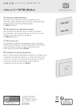
The room sensor and measuring transducer 

HYGRASGARD

®

  FSFTM - Modbus 

in the in-wall housing, optionally with potentiometer, is used to 

measure the relative humidity and  temperature of the air, and for setpoint adjustment. The following parameters are calculated internally from the 
measured values: relative humidity [%  r. H.], absolute humidity [g  ⁄ m³], mixture ratio [g  ⁄ kg], dew point temperature [°C], enthalpy [kJ  ⁄ kg] (ignoring 
atmospheric air pressure) and room temperature [°C]. The parameters are queried via the Modbus interface. 
A digital, long-term stable sensor is used for humidity and temperature measurement.  Relative humidity [%  r. H.] is the quotient of water vapour 
partial pressure divided by the saturation vapour pressure at the respective gas temperature.
The in-wall sensor is mounted in high-quality panel switch programmes, ideally of the brands Gira, Berker, Merten, Jung, Siemens or Busch-Jaeger 
(using in-wall adapters, no setpoint adjustment possible) either individually or in combination with light switches, socket outlets, etc.
It is used in non-aggressive, dust-free environments, in refrigeration, air conditioning and clean room technology, and in interior rooms, such as living 
rooms, offices, hotels, etc.  

TECHNICAL DATA

Power supply:  

24 V AC ⁄ DC (± 10 %)

Power consumption:  

< 1.1 W  ⁄  24 V DC ;  < 2.2 VA  ⁄  24 V AC

Bus parameters:


In the absence of current delivery

 (under currentless conditions) 

can be 

configured and addressed via DIP switch!

Bus  interface:  

RS 485, 

galvanically isolated, 

bus termination can be activated via DIP switch.  

Up to 32 devices possible in one segment.  
In case of a greater number of devices, RS 485 transceivers must be used.

Bus protocol: 

Modbus  (RTU-Mode), address range 0...

247

 selectable

Baud rate:  

9600, 19200, 38400 Baud

Signal filtering: 

4 s / 32 s

Data points: 

temperature [°C], relative humidity [%  r. H.],  absolute humidity [g  ⁄ m³], dew point [°C],  
mixing ratio [g  ⁄ kg], enthalpy [kJ  ⁄ kg] and setpoint potentiometer  
(no setpoint adjustment possible with Busch-Jaeger)

HUMIDITY

Sensor:  

digital humidity sensor, with integrated temperature sensor,  


low hysteresis, high long-term stability

Long-term  stability:   

± 1 %  per  year

Measuring range, humidity::  

0...100 % r. H. 

Operating range, humidity:  

0...95 % r. H.  (non-precipitating air)

Deviation,  humidity:  

typically  ± 3.0 %  (20...80 %  r. H.)  at  +25 °C,  otherwise  ± 5.0 %

TEMPERATURE

Measuring  range:  

0...+50 °C

Deviation,  temperature:   

typically  ±  0.8 K  at  +25 °C

Mounting:  

in-wall flush box  Ø 55 mm

Electrical connection:  

0.14 - 1.5 mm², via screw terminals

Ambient  temperature:   

Storage  –35...+85 °C;     
Operation  0...+50 °C

Permitted humidity:  

max. 90 % r.H., non-precipitating air

Medium:  

clean air and other non-aggressive, non-combustible gases

Protection class:   

III  (according to EN 60 730)

Protection type:   

IP 20  (according to 60 529)

Standards:  

CE-conformity, electromagnetic compatibility according to EN 61 326, EMC Directive 2014 ⁄ 30 ⁄ EU

SWITCH PROGRAMME

Manufacturer:  

GIRA System 55   
(other switch programmes, manufacturers, colours as well as prices available upon request)

Housing:  

plastic, the standard colour is pure glossy white (similar to RAL 9010) 
(other colours are available upon request with colour variants depending on the respective light switch programme)

Summary of Contents for FSFTM-Modbus

Page 1: ...relative absolute humidity dew point mixture ratio enthalpy in wall in the panel switch programme with Modbus connection F Notice d instruction Sonde d ambiance d humidit et de temp rature resp conve...

Page 2: ...GRASGARD FSFTM Modbus D G F r Ma zeichnung Dimensional drawing Plan cot Ma zeichnung Dimensional drawing Plan cot FSFTM Modbus P FSFTM Modbus 15 5 55 3 43 80 55 80 50 60 60 12 40 5 55 3 80 55 80 50 60...

Page 3: ...Busschnittstelle RS 485 galvanisch getrennt Busabschluss ber DIP Schalter aktivierbar Bis zu 32 Ger te auf einem Segment m glich Bei gr erer Anzahl von Ger ten m ssen RS 485 Transceiver eingesetzt wer...

Page 4: ...odbus 1201 9226 1000 162 FSFTM Modbus P 0 100 r H default 0 80 g kg MV 0 80 g m3 a F 0 85 kJ kg ENT 20 80 C TP 0 50 C Potentiometer Modbus 1201 9226 1400 282 Datenpunkte relative Feuchte r H absolute...

Page 5: ...sgeschwindigkeit wird ber Pos 1 und 2 des DIP Schalters B eingestellt Einstellbar sind 9600 Baud 19200 Baud oder 38400 Baud siehe Tabelle Die Parity wird ber Pos 3 des DIP Schalters B eingestellt Eins...

Page 6: ...t tzt Sub Function Code Parameter Data Type Antwort 00 Echo der Sendedaten Loopback Echodaten 01 Neustart Modbus Reset Listen Only Mode Echo Telegramm 04 Aktivierung Listen Only Mode Keine Antwort 10...

Page 7: ...etrennte Segmente aufzuteilen Die Teilnehmeradresse kann von 1 bis 247 eingestellt werden F r die Busleitung ist ein Kabel mit paarverseilter Datenleitung Spannungsversorgung und Kupferabschirmgeflech...

Page 8: ...rlegung mit stromf hrenden Leitungen ist unbedingt zu vermeiden es wird empfohlen abgeschirmte Leitungen zu verwenden dabei ist der Schirm einseitig an der DDC SPS aufzulegen Der Einbau hat unter Beac...

Page 9: ...sem Ger t entstehen sind von der Gew hrleistung und Haftung ausgeschlossen Montage und Inbetriebnahme der Ger te darf nur durch Fachpersonal erfolgen Es gelten ausschlie lich die technischen Daten und...

Page 10: ...RS 485 galvanically isolated bus termination can be activated via DIP switch Up to 32 devices possible in one segment In case of a greater number of devices RS 485 transceivers must be used Bus protoc...

Page 11: ...20 80 C TP 0 50 C Modbus 1201 9226 1000 162 FSFTM Modbus P 0 100 r H default 0 80 g kg MV 0 80 g m3 a F 0 85 kJ kg ENT 20 80 C TP 0 50 C Potentiometer Modbus 1201 9226 1400 282 Data points relative hu...

Page 12: ...ault OFF Inactive OFF The baud rate speed of transmission is set at DIP switches 1 and 2 of DIP switch block B Selectable are 9600 baud 19200 baud or 38400 baud see table Parity is set at DIP switch 3...

Page 13: ...Function Code Parameter Data Type Answer 00 Echo of transmission data Loopback Echo data 01 Restart Modbus Reset listen only mode Echo telegram 04 Activation listen only mode No answer 10 Delete coun...

Page 14: ...ribers is greater the bus must be subdivided into several segments separated by repeaters The subscriber address can be set from 1 to 247 For the bus line a twisted pair cable data line power supply l...

Page 15: ...be adhered to It is imperative to avoid parallel laying of current carrying lines We recommend to use shielded cables with the shielding being attached at one side to the DDC PLC Before mounting make...

Page 16: ...s caused by a fault in this device are excluded from warranty or liability These devices must be installed and commissioned by authorised specialists The technical data and connecting conditions of th...

Page 17: ...ble et adressable via interrupteur DIP Interface de bus RS 485 s paration galvanique terminaison de bus activable via interrupteur DIP Jusqu 32 appareils possibles sur un segment Pour un nombre sup ri...

Page 18: ...201 9226 1000 162 FSFTM Modbus P 0 100 h r default 0 80 g kg MV 0 80 g m3 a F 0 85 kJ kg ENT 20 80 C TP 0 50 C Potentiom tre Modbus 1201 9226 1400 282 Donn es humidit relative h r humidit absolue g m...

Page 19: ...B On peut r gler 9600 Baud 19200 Baud ou 38400 Baud voir tableau La parit est r gl e via la pos 3 de l interrupteur DIP B On peut r gler EVEN paire ou ODD impaire voir tableau La protection par parit...

Page 20: ...sion loopback rebouclage Donn es d cho 01 Red marrage Modbus Reset Listen Only Mode R init Mode coute Seule T l gramme d cho 04 Activation Listen Only Mode mode coute seule Pas de r ponse 10 Efface co...

Page 21: ...it tre r parti en plusieurs segments par l interm diaire de repeaters L adresse des correspondants peut tre fix e de 1 247 Pour la ligne de bus on peut utiliser un c ble avec ligne de donn es alimenta...

Page 22: ...e de temp ratures Les directives CEM celles ci sont respecter Ne pas poser les c bles de sonde en parall le avec des c bles de puissance Il est conseill d utiliser des c bles blind s ce faisant raccor...

Page 23: ...cons cutif provoqu par des erreurs commises sur cet appareil L installation et la mise en service des appareils doit tre effectu e uniquement par du personnel qualifi Seules les donn es techniques et...

Page 24: ...Merten Jung Siemens Busch Jaeger 24 10 1 1 24 2 2 24 DIP RS 485 DIP 32 RS485 Modbus RTU 0 247 9600 19 200 38 400 4 c 32 c C C Busch Jaeger 1 0 100 0 95 3 0 20 80 25 C 5 0 0 50 C 0 8 K 25 C 55 0 14 1 5...

Page 25: ...TM Modbus 60 HYGRASGARD FSFTM Modbus WG02 FSFTM Modbus FSFTM Modbus 0 100 default 0 80 MV 0 80 3 a F 0 85 ENT 20 80 C TP 0 50 C Modbus 1201 9226 1000 162 FSFTM Modbus P 0 100 default 0 80 MV 0 80 3 a...

Page 26: ...8 DIP 1 ON DIP 2 64 DIP 2 ON DIP 3 32 DIP 3 OFF DIP 4 16 DIP 4 OFF DIP 5 8 DIP 5 OFF DIP 6 4 DIP 6 OFF DIP 7 2 DIP 7 OFF DIP 8 1 DIP 8 ON 128 64 1 193 Modbus DIP 1 DIP 2 MODBUS DIP B 9600 ON OFF 1 2 3...

Page 27: ...0006 16 0 500 0 0 50 0 C 3x0007 16 0 800 0 0 80 0 3 3x0008 16 0 800 0 0 80 0 3x0009 16 0 850 0 0 85 0 08 Diagnostics 00 Loopback 01 Modbus Reset Listen Only Mode 04 Listen Only Mode 10 11 16 12 CRC 16...

Page 28: ...Modbus 32 1 247 100 Profibus Slave n MODBUS RTU Master RS 485 20 n 40 n Slave 1 Slave 2 LA LA A D1 D GND B D0 D MODBUS RTU Master Slave 1 Slave 2 5 B RBIAS RBIAS RAB RAB r AERASGARD FSFTM Modbus Rev...

Page 29: ...29 r EMV VDE VDI DDC PLC 0 5 g VDE...

Page 30: ...30 r ZVEI VDE EMV...

Page 31: ...rol their particular suitability must be verified by each customer and or end user themselves Existing property rights must be observed We warrant the faultless quality of our products as stated in ou...

Page 32: ...120 0 1 1 1 1 0 0 0 121 0 1 1 1 1 0 0 1 122 0 1 1 1 1 0 1 0 123 0 1 1 1 1 0 1 1 124 0 1 1 1 1 1 0 0 125 0 1 1 1 1 1 0 1 126 0 1 1 1 1 1 1 0 127 0 1 1 1 1 1 1 1 128 1 0 0 0 0 0 0 0 129 1 0 0 0 0 0 0 1...

Reviews: