12
www.sc-black.com
SECTION 2: INSTALLATION AND SETUP
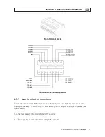
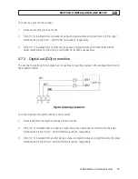
2. Strip 1/4” of insulation from the wires speaker signal and ground wires and insert them into the
lower terminal block on the AOut and AOut Gnd pins, respectively.
3. Strip 1/4” of insulation from the microphone signal and ground wires and insert them into the upper
terminal block on the Ain and Ain Gnd pins, respectively.
2.7.2 Sensor in (DI) connection
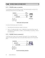
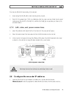
The encoder provides two input channels for sensors. The sensors can be either both voltage type or
both relay type sensors, but not one of each. For voltage type sensors, see Specifications for allowable
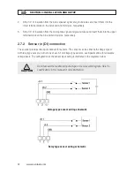
voltage levels. The configuration of the sensor input wiring is illustrated in the diagrams below.
CAUTION
Do not exceed the maximum input voltage or the relay switching rate. Refer to
specifications in this manual for more information.
Voltage type sensor wiring schematic
Relay type sensor wiring schematic

