4
ENGLISH
TECHNICAL DATA
Type Model No..............................................RSH2400RG
Voltage..................................................230-240VAC 50Hz
Rated Power......................2400W (S6-40%) 2200W (S1)
Max. Idle Speed...............................................4500 min
-1
Max. Cutting Diameter ....................................Max. 40mm
Weight ................................................................... 13.5Kg
Measured sound pressure level ..............LPA: 95.6 dB(A)
KPA: 2.0dB(A)
Measured sound power level................LWA: 106.2 dB(A)
KWA: 2.0dB(A)
NOTE:
n
The S6-40% indicates a load profile of 4 min load and
6 min idle time. For practical application, continuous
operation is permitted.
n
The Max Cutting Diameter depends on the hardness
of the wood.
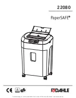
DESCRIPTION
Figure 1
1. Feeding chute
2. Shredder body
3. Cover locking knob
4. Discharge chute
5. Wheel supports protector
6. Transportation wheel
7. Motor cover
8. Mains cable and plug
9. Transportation handle
Figure 2
10. Leg
11. Protector fixed screw
12. End frame
13. Nylon nut
14. Axle tube
15. Washer
16. Wheel bush
17. Washer
Figure 3
18. Spanner I (with hex key)
19. Spanner II (with crossed key)
20. Plunger
Figure 5
21. Leg fixed screw
Figure 6
22. Leg fitting hole
Figure 7
23. Indication lamp
24. Overload protection button
25. On/Off switch
Figure 8
26. First lock
27. Key
28. Second lock
Figure 9
29. Safe blockage
30. Cutting device
ASSEMBLY
FITTING THE TRANSPORTATION WHEELS
WARNING
You may need assistance when lifting the
machine out of the box and assembling.
NOTE:
The legs should be splayed out at the bottom to
give stability to the unit.
1. Position the axle tube between the two legs.
2. Slide the axle tube through the hole in one of the legs
then through the axle tube and out through the hole in
the other leg. (See figure 4)
3. Position the washers and wheel bushes on each end
of the axle.
4. Push the wheels onto each end of the axle.
5. Position the remaining washers and the locking nuts
on each end of the axle and tighten both the wheel
nuts using spanner I and spanner II.
NOTE:
One spanner is used to fix the nylon nut on one
side, and the other spanner is used to lock the nylon
nut on the other side.
6. Insert the legs into the end frame and lock the screw.
(See figure 5)
NOTE:
The wheels must be fitted the correct way round
to allow the nuts to tighten on each end of the axle.
FITTING THE LEG
1. Turn the shredder over onto its front to reveal the
wheel support fixing holes at the underside of the
shredder body.
2. Push the leg into the hole in the shredder body. (See
figure 6)