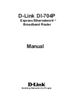
background image

11

LOCKING

ARM

DEPTH

ADJUSTMENT

RING

OPERATION

WARNING:

Never connect the router to power supply when you are
assembling parts, making adjustments, installing or re-
moving cutters, or when not in use. Disconnecting the
router prevents accidental starting that could cause seri-
ous injury.

REMOVING AND INSTALLING THE ROUTER BASE

TO SWITCH FROM THE FIXED BASE OR D-HANDLE BASE
TO THE PLUNGE BASE

See Figure 4.

TO REMOVE THE FIXED OR D-HANDLE BASE:

1. Unplug the router.

WARNING:

Failure to unplug the tool could result in accidental starting
causing serious injury.

2.

Place the router upside down with the Ryobi label away
from you.

3.

Loosen the locking arm on the base.

4.

Depress and hold the gold spindle lock button. The gold
spindle lock button will not depress fully unless it is in
line with the hole in the collet.

5.

If the gold spindle lock button does not depress fully,
turn the collet nut while depressing the gold spindle lock
button. As they align, the gold spindle lock button will
depress fully.

6.

Turn the depth adjusting ring counterclockwise until the
motor is to its highest position. 

NOTE:

 As the motor is

rising, the gold spindle lock button has to be depressed
until it clears the rear window.

7.

Align the indicator arrow on the depth adjustment ring
with the indicator point on the base.

8.

Pull the base until it dislodges from the motor housing.

TO INSTALL THE PLUNGE BASE

1.

Unplug the router.

2.

Place the plunge base on a flat surface.

3.

Loosen the locking knob.

4.

Align the groove in the motor housing with the rib inside
the base. 

NOTE:

 The rib is located on the inside of the

base in line with the handle.

5.

Depress and hold the gold spindle lock button.

6.

Slide the motor housing into the base.

7.

Tighten the locking knob.

CAUTION:

Do not tighten the locking knob without the motor installed
in the base. Failure to heed this caution may result in
permanent damage to the locking mechanism.

Fig. 4

GOLD

SPINDLE

LOCK

BUTTON

Fig. 5

RIB INSIDE THE  BASE

GROOVE IN

MOTOR

HOUSING

1

2

0

15/32

1/32

INDICATOR

POINT

INDICATOR

ARROW

DEPTH

ADJUSTMENT

RING

Summary of Contents for R181DB1

Page 1: ...been engineered and manufactured to our Ryobi s high standard for dependability ease of operation and operator safety When properly cared for the router will give you years of rugged trouble free per...

Page 2: ...Operation 10 22 Maintenance 23 Accessories 23 Parts Ordering and Service 24 TABLE OF CONTENTS INTRODUCTION This router has many features for making its use more pleasant and enjoyable Safety performan...

Page 3: ...r finger on the switch or plugging in tools that have the switch on invites accidents Remove adjusting keys or wrenches before turning the tool on A wrench or a key that is left attached to a rotating...

Page 4: ...for an extension cord 50 feet or less in length A cord exceeding 50 feet is not recom mended If in doubt use the next heavier gage The smaller the gage number the heavier the cord An undersized cord w...

Page 5: ...tions Alert Do not expose to rain or use in damp locations To reduce the risk of injury the user must read and understand the operator s manual before using this product Eye Protection Always wear saf...

Page 6: ...g signal words and meanings are intended to explain the levels of risk associated with this product DANGER Indicates an imminently hazardous situation which if not avoided will result in death or seri...

Page 7: ...ugged into an outlet double check the power supply EXTENSION CORDS When using a power tool at a considerable distance from a power source be sure to use an extension cord that has the capacity to hand...

Page 8: ...adjust the motor speed to required job conditions The variable speed control is located on the front of the router and allows the router to develop a no load speed from 15 000 to 25 000 min LOCKING AR...

Page 9: ...sistance WARNING If any parts are missing do not operate the tool until the missing parts are replaced Failure to do so could result in possible serious personal injury PACKING LIST Router Fixed Base...

Page 10: ...collet nut Refer to Removing Inserting Cutters later in this manual 3 Set the desired depth of cut Refer to Adjusting Depth of Cut later in this manual 4 Secure the workpiece 5 Plug the router into a...

Page 11: ...button As they align the gold spindle lock button will depress fully 6 Turn the depth adjusting ring counterclockwise until the motor is to its highest position NOTE As the motor is rising the gold s...

Page 12: ...le depressing the gold spindle lock button As they align the gold spindle lock button will depress fully 6 Remove the motor housing from the plunge base NOTE As the motor is being removed from the bas...

Page 13: ...ptions To remove the cutter Remove the cutter from the collet To insert the cutter a Insert the shank of the cutter until the shank bottoms out then pull it out 1 16 in 1 6 mm to allow for expansion w...

Page 14: ...that cuts be made at a depth not exceeding 1 8 in 3 2 mm and that several passes be made to reach deeper cuts Adjusting the depth of cut for the plunge router is different from adjusting the depth of...

Page 15: ...bar down so it touches the depth stop 8 Tighten the stop bar knob securely 9 Set the depth indicator to zero 10 Loosen the stop bar knob 11 Set the depth indicator to the desired depth of cut Note Ea...

Page 16: ...eness of your cut if you are not prepared Such a kickback is always in the direction opposite to the direction of bit rotation To guard against such a kickback plan your setup and direction of feed so...

Page 17: ...smooth cuts if allowed to run freely without the overload of a forced too fast feed Three things that cause force feeding are bit size depth of cut and workpiece characteristics The larger the bit or...

Page 18: ...he bit 1 8 in for each new pass In order to save time do all the cutting necessary at one depth setting before lowering the bit for the next pass This will also assure a uniform depth when the final p...

Page 19: ...When freehand routing we suggest the following Draw or layout the pattern on workpiece Choose the appropriate cutter NOTE A core box or V groove bit is often used for routing letters and engraving ob...

Page 20: ...der the workpiece to act as a guide This guide board must have exactly the same contour straight or curved as the workpiece edge If the guide is positioned so that its edge is flush with the workpiece...

Page 21: ...ed depth and lock the depth lock Adjust the subbase so that the end of the cutter is centered in the collar of the bushing Tighten the four subbase screws securely WARNING Failure to tighten screws co...

Page 22: ...router WARNING Failure to unplug your router could result in accidental starting causing serious injury Slide the two straight guide mounting posts into the holes in the side of the router base Set t...

Page 23: ...sharp Remove all accumulated pitch and gum from cutters after each use When sharpening cutters sharpen only the inside of the cutting edge Never grind the outside diameter Be sure when sharpening the...

Page 24: ...525 2579 for your nearest Ryobi Authorized Service Center You can also check our Web site at www ryobitools com for a complete list of Authorized Service Centers MODEL NO AND SERIAL NO The model numbe...

Reviews: