background image

DESCRIPTION OF THE INSTRUMENT 

Axio Lab.A1 

System overview 

Carl Zeiss 


04/2013 430037-7144-001 

17 


Summary of Contents for Axio Lab.A1

Page 1: ...Operating Manual Axio Lab A1 Ryf AG Bettlachstrasse 2 2540 Grenchen tel 032 654 21 00 fax 032 654 21 09 www ryfag ch...

Page 2: ...ention of this copyright are liable to pay compensation for damages All rights reserved including rights created by patent grant or registration of a utility model All names of companies and products...

Page 3: ...ted light conoscopy 34 2 4 7 Ergo stands with T V certificate Ergonomically tested 36 2 5 Control and functional elements on optional components 37 2 5 1 Tubes photo tubes 37 2 5 2 Microscope stages 4...

Page 4: ...light 72 4 1 1 Adjusting the transmitted light brightfield according to K HLER 72 4 1 2 Adjusting the transmitted light darkfield according to K HLER 75 4 1 3 Setting the transmitted light phase cont...

Page 5: ...adjustment 40 Fig 2 14 Mechanical stage 75x30 R with specimen holder 41 Fig 2 15 Mechanical stage 75x30 R ergonomic with stationary drive 41 Fig 2 16 Mechanical stage reflected light 75x30 R with spec...

Page 6: ...rier 74 Fig 4 3 Center darkfield stop on condenser achromatic aplanatic 0 9 H D Ph DIC 76 Fig 4 4 Centering the phase stop bright ring in condenser to the phase ring dark ring in objective 77 Fig 4 5...

Page 7: ...surface CAUTION UV radiation emitted CAUTION Disconnect the instrument from the power supply before opening CAUTION This symbol indicates a potential hazard to the instrument or system NOTE This symbo...

Page 8: ...tances that could be hazardous to health Make sure to observe all legal regulations particularly the relevant national accident prevention regulations when handling such substances Dirt and dust may i...

Page 9: ...ol W Immersol 518 N immersion oil irritates the skin Avoid any contact with skin eyes and clothing In the case of inadvertent skin contact wash the oil off with plenty of water and soap In the case of...

Page 10: ...10 430037 7144 001 04 2013 Warning labels on Axio Lab A1 stands Warning label Hot surface Affixed to all stands with transmitted light illumination Fig 1 1 RADIATION and LED APERTURE warning labels o...

Page 11: ...INTRODUCTION Axio Lab A1 Notes on instrument safety Carl Zeiss 04 2013 430037 7144 001 11 Fig 1 2 Hot surface below warning label on Axio Lab A1 for reflected light...

Page 12: ...and microscopes T V certificate ID 0000025994 Ergonomically tested prescribes the distance of control elements from the table user and between instruments Furthermore it defines a broad adjustment ra...

Page 13: ...nty The manufacturer guarantees that the instrument has no material or production defects when delivered Any defects occurring must be reported without delay every effort must be made to minimize dama...

Page 14: ...logy Analysis of human blood and tissue samples Typical material analysis applications of Axio Lab A1 microscopes include Metallographic laboratories Automotive industry Microsystems engineering Geosc...

Page 15: ...xed stage drive Vertical and friction adjustable stage drives Optional use of fine focusing knobs in standard form or as a jog shuttle knob Special ergonomic arrangement of the three main control elem...

Page 16: ...DESCRIPTION OF THE INSTRUMENT Carl Zeiss System overview Axio Lab A1 16 430037 7144 001 04 2013 2 2 System overview...

Page 17: ...DESCRIPTION OF THE INSTRUMENT Axio Lab A1 System overview Carl Zeiss 04 2013 430037 7144 001 17...

Page 18: ...DESCRIPTION OF THE INSTRUMENT Carl Zeiss System overview Axio Lab A1 18 430037 7144 001 04 2013...

Page 19: ...DESCRIPTION OF THE INSTRUMENT Axio Lab A1 System overview Carl Zeiss 04 2013 430037 7144 001 19...

Page 20: ...DESCRIPTION OF THE INSTRUMENT Carl Zeiss System overview Axio Lab A1 20 430037 7144 001 04 2013...

Page 21: ...d accessories approx 8 to 20 kg Ambient conditions Shipping in packaging Permissible ambient temperature 40 to 70 C Storage Permissible ambient temperature 10 to 40 C Permissible humidity without cond...

Page 22: ...cted light fluorescence with replaceable LED modules Wavelengths optional 365 380 455 470 505 530 590 615 625 nm or neutral white 540 580 nm LED classification LED Risk Group 2 to IEC 62471 Axio Lab A...

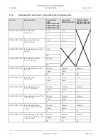
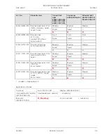
Page 23: ...85 425520 9030 000 Binocular photo tube 20 23 100 100 20 none 442 481 425520 9040 000 Bin ergo tube 100 100 angle adjustable upright image 5 30 Angle 395 537 425520 9050 000 Bin ergo tube 15 23 50 50...

Page 24: ...nomic tube 8 38 20 Small M 425522 9030 000 Binocular photo tube 8 38 20 50 50 Medium M 425522 9040 000 Binocular ergonomic tube 8 33 22 Medium Medium Medium Spacer Spacer M M M 425520 9000 000 Binocul...

Page 25: ...25520 9100 000 Binocular photo tube 20 23 Pol 100 100 Medium Medium Medium Spacer Spacer M M M 425511 0000 000 Binocular ergo tube 20 23 reverse image 44 mm height Medium Medium Medium Spacer Spacer M...

Page 26: ...T V Rheinland and granted for the following two basic configurations Transmitted light stand with ergo stage and comfortable ergonomic tube Reflected light fluorescence stand with ergo stage and comf...

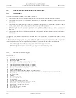
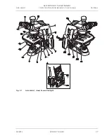
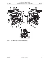
Page 27: ...DESCRIPTION OF THE INSTRUMENT Axio Lab A1 Control and functional elements on microscope Carl Zeiss 04 2013 430037 7144 001 27 Fig 2 1 Axio Lab A1 stand transmitted light...

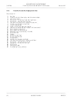
Page 28: ...condenser right side 8 Luminous field diaphragm 9 Locking screw for rotary table arrests rotation 10 Condenser with aperture diaphragm optional with modulator disk 11 Rotary stage lock in stage carrie...

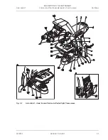
Page 29: ...DESCRIPTION OF THE INSTRUMENT Axio Lab A1 Control and functional elements on microscope Carl Zeiss 04 2013 430037 7144 001 29 Fig 2 2 Axio Lab A1 stand transmitted light polarization...

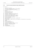
Page 30: ...adjustment right side 12 Drive knob for mechanical stage adjustment in X direction 13 Drive knob for mechanical stage adjustment in Y direction 14 Drive knob for vertical adjustment of condenser right...

Page 31: ...DESCRIPTION OF THE INSTRUMENT Axio Lab A1 Control and functional elements on microscope Carl Zeiss 04 2013 430037 7144 001 31 Fig 2 3 Axio Lab A1 stand transmitted and reflected light fluorescence...

Page 32: ...using drive fine adjustment right side finger wheel 9 Focusing drive coarse adjustment right side 10 Drive knob for mechanical stage adjustment in X direction 11 Drive knob for mechanical stage adjust...

Page 33: ...DESCRIPTION OF THE INSTRUMENT Axio Lab A1 Control and functional elements on microscope Carl Zeiss 04 2013 430037 7144 001 33 Fig 2 4 Axio Lab A1 stand reflected light...

Page 34: ...rture diaphragm optional with modulator disk 14 Rotary stage Pol with specimen holder 15 Slot for 6x20 slider 16 Setting wheel for direction of oscillation of analyzer 17 Setting wheel for focusing of...

Page 35: ...DESCRIPTION OF THE INSTRUMENT Axio Lab A1 Control and functional elements on microscope Carl Zeiss 04 2013 430037 7144 001 35 Fig 2 5 Axio Lab A1 stand transmitted light conoscopy...

Page 36: ...Fig 2 6 1 Binocular ergo tube 8 33 50 mm vertically adjustable 2 Mechanical stage 75x30 ergonomic with stationary drive 3 Stand for transmitted light and reflected light fluorescence Fig 2 6 Axio Lab...

Page 37: ...rected using a shift knob to either the eyepieces or the mounted camera Shift knob Fig 2 8 2 to front eye symbol 100 light to eyepieces Shift knob Fig 2 8 2 to the rear camera symbol 100 light to came...

Page 38: ...be ergo photo tube 8 38 20 These tubes are designed for a field of view of 20 The viewing angle can be continuously adjusted between 8 and 38 by swiveling the binocular section Fig 2 10 1 The splittin...

Page 39: ...he viewing angle The latter can be continuously varied within a range of 0 mm to 50 mm with the aid of the rotary knobs Fig 2 11 1 The setting can be read off a vertical scale Fig 2 11 4 In addition a...

Page 40: ...e binocular section from the lower to the upper observation position Continuous height adjustment is achieved by means of the rotary knobs Fig 2 12 1 and Fig 2 13 1 The adjustment range of the ergo ph...

Page 41: ...ools Fig 2 14 8 are located in the upper drive knob Vernier scale for display of adjustment range in X Fig 2 14 3 and Y direction Fig 2 14 4 Drive knobs on right R or left L side depending on model Fu...

Page 42: ...mounting the specimen guide on the rotary stage Specimen guide equipped with specimen holder which can be shifted in X and Y direction using drive knobs Fig 2 17 3 and 2 The shift in X and Y directio...

Page 43: ...sk Fig 2 19 3 for Brightfield H Darkfield D Phase contrast Ph 1 Ph 2 Ph 3 Position adjustment of modulator disk by turning knurled ring Fig 2 19 2 This condenser is also available without modulator di...

Page 44: ...be centered with the centering screws For this purpose the condenser should be centered on the other objectives without the overview fixture With the overview fixture attached it can be mounted on th...

Page 45: ...with M27 threaded insert for four or five objectives Quick change of objectives by turning nosepiece on knurled ring Fig 2 24 2 Incorporates slot Fig 2 24 3 for 6x20 slide compensators analyzers quart...

Page 46: ...d components 3 1 1 Unpacking and setting up microscope stand x Remove all components from the packaging and check that all components described on the delivery note are present x Set up microscope sta...

Page 47: ...the corresponding notes in the system overview Section2 2 The base plate is not required for binocular tube or photo tube 30 20 425522 9000 000 and 425522 9010 000 or binocular tubes 20 23 and 30 23 4...

Page 48: ...Fig 3 5 1 at an angle insert it with the dovetail ring into the stand mount Fig 3 5 4 and turn into a horizontal position Rotate the binocular tube into the desired observation position and re tighten...

Page 49: ...nocular sockets for observing aperture phase and darkfield stops or for centering phase stops Focusing on these apertures is possible using the adjustable eye lens x The auxiliary microscope Fig 3 6 3...

Page 50: ...5 Screwing in objectives x Move mechanical stage with stage carrier to lower stop x Remove the dust caps Fig 3 8 5 from the openings in the nosepiece x Remove objectives Fig 3 8 4 from the case and s...

Page 51: ...om below until it also securely engages with the lower spring clips of the reflector turret The position number of the P C module is shown on the right hand side of the reflector turret adjacent to th...

Page 52: ...ig 3 10 3 Allen wrench x Remove stage Fig 3 10 1 upwards from the stage carrier 3 1 7 2 Installing the stage x Place stage Fig 3 10 1 onto stage carrier Fig 3 10 2 in such a manner that the threaded h...

Page 53: ...Fig 3 11 x It should not be shifted more than one revolution 2 Y drive x Push drive knob for Y adjustment Fig 3 11 1 right to the top x Insert the supplied adjusting pin Fig 3 11 5 into the hole of th...

Page 54: ...groove of the dovetail stage bottom on spring loaded pin Fig 3 12 7 x Attach the rotary stage with the clamp screw Fig 3 12 8 pointing to the front right x Press the rotary stage Pol to the front aga...

Page 55: ...K HLER illumination on the microscope must be adjusted before centering the stage see Section 4 1 1 x Turn the nosepiece to swing the non centring objective mount x For centering the stage use a cont...

Page 56: ...cle x First turn the nosepiece to swing the non centering objective mount Center the rotary stage for the non centering objective mount as described under 3 1 8 5 x Turn the nosepiece to move a center...

Page 57: ...iew fixture make sure that this does not come to rest on the luminous field diaphragm x Insert the condenser Fig 3 15 8 or 9 between the condenser carrier Fig 3 15 3 and the stage carrier Fig 3 15 1 I...

Page 58: ...p plug Fig 3 17 2 from the lighting unit Fig 3 17 3 x Press the loops Fig 3 18 1 on the securing clip Fig 3 17 1 of the lamp holder together and swing it out to the front x When changing the lamp remo...

Page 59: ...ing unit Fig 3 19 1 Ensure that it engages properly to avoid bending the pins x Insert the cable of the lamp plug into the stand so that it is not damaged when the cover is mounted x Insert the lower...

Page 60: ...ig 3 21 3 x Position the halogen lamp Fig 3 22 2 on the contact surface of the lamp holder lamp will be held secure by the groove x Press the securing clip Fig 3 22 1 on both sides of the lamp holder...

Page 61: ...nnecting socket while pressing the notched lever on the plug Remove the securing clip Fig 3 24 3 of the module holder upwards and pull out the LED module Fig 3 24 2 x Press the securing clip Fig 3 25...

Page 62: ...arizer D or filter holder x Lift the condenser carrier together with its drive knob upwards as far as it will go x If necessary unscrew locking and holding pins together with the overview fixture from...

Page 63: ...fixture with the angled adjusting lever Fig 3 27 6 into the front left threaded hole below the condenser carrier as far as it will go x Screw the locking pin Fig 3 27 8 with adjusting lever Fig 3 27 7...

Page 64: ...28 5 of the condenser scale segment Fig 3 28 3 with a SW 3 screwdriver and pull the scale segment out to the front x Insert the modulator disk Fig 3 28 4 with the two pronged fork opening at the front...

Page 65: ...ains switch x Adjust image brightness Fig 3 31 3 using the brightness control To do this take hold of the recessed grips of the rotary knob with the fingertips and turn it to the desired position Only...

Page 66: ...matological histological and cytological examinations over a period of several hours With this regular use of the light microscope for extended periods it is particularly important to keep the burden...

Page 67: ...tation in stages by selecting an adjustable ergo tube or special ergonomically designed table with fixed stage drive 3 5 3 Ergonomic configuration of the microscope workstation In addition to the use...

Page 68: ...The upper part of the body should be as upright as possible DIN EN 1335 1 Office work chairs The seat and backrest of the office swivel chair should satisfy ergonomic requirements and support dynamic...

Page 69: ...swivel chairs Accordingly eyepiece viewing should be achieved by swinging the binocular part up or down for fixed observation tubes or by continuous adjustment of an inclinable eyepiece and or viewin...

Page 70: ...angle which may be stationary or variable depending on the model With an interpupillary distance of 65 mm and a tube viewing angle of 30 this adjustable height difference is approx 40 mm Binocular er...

Page 71: ...ure of the eyepiece reticle with the focusable eye lens of the adjustable eyepiece x Focus on the microscopic image of a loaded specimen with the focusing drive while observing with the eyepiece conta...

Page 72: ...elow in Section 4 1 1 3 Setting transmitted light brightfield according to K HLER 2 Instrumentation for transmitted light brightfield The equipment of every Axio Lab A1 microscope except the stand for...

Page 73: ...sting lever Fig 4 2 4 to approx 2 3 4 5 of the diameter of the exit pupil of the objective Fig 4 1 E In most applications this aperture diaphragm setting provides optimum contrast at almost ideal reso...

Page 74: ...ig 4 2 1 of the height stop using a SW 3 ball headed screwdriver x Use focusing drive to focus on the specimen x Close luminous field diaphragm and focus it by turning the vertical control Fig 4 2 2 o...

Page 75: ...r with dry darkfield Ultra condenser 3 Adjusting the transmitted light darkfield x Adjust the brightness according to K HLER analogously to the method for the transmitted light brightfield Instead of...

Page 76: ...mediate image in order to transform small phase differences into differences in intensity and color which are visible to the human eye High intensity direct light components are attenuated with the op...

Page 77: ...e ring in the exit pupil of the objective x If congruence is not perfect Fig 4 4 A use the two SW 1 5 hexagonal screwdrivers Fig 4 3 1 and 4 to turn the two centering screws Fig 4 3 2 and 3 to recente...

Page 78: ...ntation of the specimen interference colors ranging from gray mostly with biological specimens to white yellow red and blue appear in this process These interference colors can be of the first or any...

Page 79: ...e does not already have an analyzer The field of view will appear dark due to the crossed polarizers With screw on analyzers care must be taken to ensure that they are aligned with polarizer D i e cro...

Page 80: ...ion from one marking to the next is 15 The 45 position is at the third marking calculated from the 0 marking As a further reference point for the correct position of the lever the Greek letter O has b...

Page 81: ...ive index in relation to the morphological directions e g of crystal surfaces crystal needles or fibers provides an important criterion for recognition It is also employed for the diagnosis of biocrys...

Page 82: ...ance on the binocular tube as the the angle of the crossline reticle to the fiber will be changed x Now turn the stage on by 45 so that the longitudinal axis of the fiber is oriented NE SW Fig 4 8 The...

Page 83: ...compensator O i e in NW SE direction the path difference of the compensator O e g grayish white 150 nm is subtracted from the path difference of the compensator red 550 nm In this case the interferenc...

Page 84: ...site for occurrence of the color change effect may be the evaluation in two specimen positions rotated at an angle of 90 from one another plus a centered stage The suitable compensator is Tilting comp...

Page 85: ...in analyzer in Axio Lab A1 tubes 3 Setting the microscope x Set the microscope as in the transmitted light brightfield according to K HLER see Section 4 1 1 x Center rotary stage Pol or objective if...

Page 86: ...ter the above adjustment x Reinsert the specimen to be examined In their interference color dependent on material specimen thickness and orientation the specimens appear constant and independent of st...

Page 87: ...ture 1 Application The crystal diagnosis is for determining the optical character of transparent and weakly absorbent crystals This method is also referred to as conoscopy Its main application is the...

Page 88: ...luar 40x 0 9 Pol and focus with the focusing drive x If necessary close the luminous field aperture to avoid superimposition of the axial figure by axial figures of neighboring crystals The smallest c...

Page 89: ...ess favourable sections in which the cross hair center is optically uniaxial or the isogyres are optically biaxial specimens outside the objective pupil an assessment is possible as follows x If the b...

Page 90: ...tated through 360 between crossed polarizers Depending on birefringence thickness and orientation of the specimen interference colors ranging from gray mostly with biological specimens to white yellow...

Page 91: ...nisotropic substances may also remain dark if an isotropic direction e g of optically uniaxial or biaxial crystals is oriented parallel to the direction of observation 4 1 6 2 Determination of gout an...

Page 92: ...n of nJ and nJ direction of oscillation with the absolutely or relatively highest refractive index and nD and nD direction of oscillation with the absolutely or relatively lowest refractive index in r...

Page 93: ...tance on the binocular tube as the the angle of the crossline reticle to the fiber will be changed x Now turn the stage on by 45 so that the longitudinal axis of the fiber is oriented NE SW Fig 4 15 T...

Page 94: ...nsator O i e in NW SE direction the path difference of the compensator O e g grayish white 150 nm is subtracted from the path difference of the compensator red 550 nm In this case the interference col...

Page 95: ...ce of the color change effect may be the evaluation in two specimen positions rotated at an angle of 90 from one another plus a centered stage The suitable compensator is tilting compensator B 0 5 O o...

Page 96: ...plate 3 Setting the microscope x Set the microscope as in the transmitted light brightfield according to K HLER see Section 4 1 1 x Center rotary stage Pol or objective if this has not already been d...

Page 97: ...until after the above adjustment x Reinsert the specimen to be examined In their interference color dependent on material specimen thickness and orientation the specimens appear constant and independ...

Page 98: ...4 1 7 1 Application The crystal diagnosis is for determining the optical character of transparent and weakly absorbent crystals This method is also referred to as conoscopy Its main application is the...

Page 99: ...tary knob A is set to the off position if it is not already at the off position rotary knob BL is automatically carried x Place a selected crystal in the center of the crossline reticle x Swivel in ob...

Page 100: ...tion of motion at insertion Direction of movement O 4 plate position of black spots Fig 4 18 Determining the optical character In the case of less favorable sections in which the cross hair center is...

Page 101: ...ith the stand for reflected light Reflector module brightfield ACR P C for reflected light in the reflector turret 3 Setting the reflected light brightfield The microscope has been started up correctl...

Page 102: ...most ideal resolution and is therefore the best compromise for the human eye x Then reinsert the eyepiece adjust the focus with the coaxial coarse and fine focusing knob and adjust the brightness to t...

Page 103: ...cted light Epiplan Neofluar EC Epiplan Neofluar Epiplan objectives with the additional designation HD Reflector module darkfield ACR P C for reflected light The stand for reflected light is equipped w...

Page 104: ...ecimen surfaces which otherwise would be unavoidable 2 Instrumentation Observations in the reflected light darkfield can only be made on Axio Lab A1 microscopes for reflected light Rotary stage Pol Ep...

Page 105: ...excitation light sources in the Axio Lab A1 program 2 Instrumentation Observations in reflected light fluorescence can only be made on Axio Lab A1 microscopes for reflected light and reflected light f...

Page 106: ...void dazzling when switching between the LEDs the brightness should be reduced slightly beforehand x Set the FL TL toggle switch to position FL reflected light fluorescence x Adjust the light intensit...

Page 107: ...cotton cloth and optical cleanser L This cleaning agent is manufactured from 85 vol gasoline and 15 vol isopropyl alcohol IPA The components are also known by the following names Gasoline rubbing alc...

Page 108: ...ct the instrument from the power supply before replacing fuses If the fuses fail the reason must first of all be ascertained and technical problems properly remedied The fuse box is located on the rea...

Page 109: ...ount Low resolving power and poor image contrast Aperture diaphragm not correctly adjusted Set the aperture diaphragm as per 2 3 rule or the specimen features see p 72 ff The condenser has not been co...

Page 110: ...e Eyepiece distance interpupillary distance is not adjusted correctly Adjust the interpupillary distance correctly see p 70 Focusable eyepieces are not adjusted correctly Adjust the focusable eyepiece...

Page 111: ...lamp see p 58 Fuses are defective Replace fuses see p 108 Installed electrical equipment may be defective Call in the service personnel to check components and replace if necessary see p 112 No voltag...

Page 112: ...imum setting and trouble free function of your microscope over a longer period of time we recommend that you enter into a service maintenance agreement with Carl Zeiss For subsequent orders or when se...

Page 113: ...European standard Ergo Ergonomic FL Fluorescence foc focusable fot photographic H brightfield IEC International Electrotechnical Commission IP Internal protection through housing ISO International Sta...

Page 114: ...34 Centering screw for condenser 26 28 30 34 Checking the instrument 108 Circular polarization contrast 85 96 Coarse adjustment 26 28 30 32 34 Color charts 83 94 Color glass holder 77 Comfortable erg...

Page 115: ...105 Focusing drive 26 28 30 32 34 74 Friction torque 53 Front lens 57 72 G Gout 80 91 H Halogen lamp 12 V 50 W 60 Height stop on condenser carrier 74 I Industrial property rights 118 Instrument care...

Page 116: ...1 Push click module 51 R Reflected light 30 32 101 103 104 105 Reflected light brightfield 101 Reflected light darkfield 103 Reflected light fluorescence 105 Reflected light illumination 30 32 Reflect...

Page 117: ...ed light illumination 30 34 Transmitted light lamp 26 28 Transmitted light phase contrast 76 Transmitted light polarization 78 90 Troubleshooting 109 Tube 26 28 30 32 34 37 49 T V certificate 67 U Unp...

Page 118: ...property rights Axio Lab A1 118 430037 7144 001 04 2013 6 3 Industrial property rights Instruments instrument components or methods described in this manual are protected by the following patents see...

Reviews: