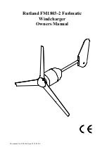
Rutland FM1803-2
Installation & Operation
Document No: SM-146 Issue D 14.03.08
Marlec Engineering Co Ltd
6
SYSTEM DESCRIPTION & PRINCIPLE OF OPERATION
Aerofoil Blades & Rotor
The 1803 rotor consists of 3 aerofoil blades rigidly fixed to a hub. The blades are at
an optimum fixed pitch for variable speed operation over a wide wind speed range.
Generator
The rotor is rigidly attached to the generator shaft providing direct drive to the 3
phase brushless permanent magnet ac generator, producing variable frequency ac at
approx 120v L-L under normal conditions.
Note: the generator must not be
allowed to run open circuit since high voltages can be generated.
Yaw system
The complete wind generator assembly is mounted on yaw bearings allowing free
rotation on it’s vertical axis to enable it to respond to changes in wind direction. The
yaw assembly also includes a slipring & brush system to transmit the generated
current to the fixed transmission cable while allowing free 360° yaw rotation.
Tail assembly
The inclined tail fin is hinged to the rigid tail boom on durable sleeve bearings.
The tail is designed to direct the turbine into the main direction of wind at wind
speeds up to approx 35mph, above this the automatic ‘furling’ mechanism will turn
the generator at an angle to the wind to protect the generator, turbine & supporting
structure from severe winds. During furling the output power will be reduced. When
the high wind subsides, the tail assembly will automatically return the turbine to
normal operation. In turbulent conditions the system may be seen to repeat this
cycle many times.


