Ruijie RG-AP850-I-V2 Series Hardware  Installation And Reference Manual Download Page 21

·


Hardware Installation and Reference Guide                                                                                                            Troubleshooting 


6  Troubleshooting 

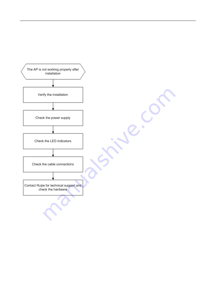
6.1  Troubleshooting Flowchart 


6.2  Troubleshooting 

LED does not light up after the AP is powered on 

1)  If you use PoE power supply, verify that the power source is IEEE 802.11af compliant; then verify that the cable is 

properly connected.   

2)  If you use a power adapter, verify that the power adapter is connected to an active power outlet; then verify that the 

power adapter works properly. 

Ethernet port is not working after the Ethernet port is connected 

Verify that the device at the other end of the Ethernet cable is working properly. And then verify that the Ethernet cable is 

capable of providing the required data rate and is properly connected.     

Wireless client cannot find the AP 

Summary of Contents for RG-AP850-I-V2 Series

Page 1: ...Ruijie RG AP850 I V2 Series Access Points Hardware Installation and Reference Guide V1 00...

Page 2: ...or by any means without the prior written consent of Ruijie Networks is prohibited Exemption statement This document is provided as is The contents of this document are subject to change without any n...

Page 3: ...tal ruijienetworks com Community https community ruijienetworks com Technical Support Email service_rj ruijienetworks com Skype service_rj ruijienetworks com Related Documents Documents Description Co...

Page 4: ...s and WiFi hotspots 1 1 Technical Specifications Table 1 1 RG AP850 I V2 Technical Specifications Model RG AP850 I V2 RF 2 4G 4 4 MU MIMO 5 2G 4 4 MU MIMO 5 8G 2 2 MIMO Transmission Protocol Tri radio...

Page 5: ...best performance it is recommended to adopt 802 3at PoE power supply When receiving 802 3at PoE power supply the AP comes up normally If powering capacity is enabled on the LAN3 port Radio 3 works wit...

Page 6: ...one USB port and one reset button Figure 1 1 Appearance of the RG AP850 I V2 Note 1 LED Indicator 2 Security lock 3 USB port 4 Reset button 5 Console Port 6 LAN3 IoT port 7 LAN2 port 8 LAN1 PoE port 9...

Page 7: ...with the AP Double blinking red 3Hz on and off for 2 cycles alternately Locating AP Reset button Pressed for less than 2s Restarts the AP Pressed for more than 3s Restores the factory default setting...

Page 8: ...Installation and Reference Guide Product Overview 1 5 Cooling Solution The AP features a fanless design Leave sufficient space surrounding the AP when installing the AP to permit proper airflow for ve...

Page 9: ...Do not subject the AP to unstable voltage vibration and noises Keep the AP at least 500 meters away from the ocean and do not face it towards the sea breeze The installation site should be free from w...

Page 10: ...ay lead to changes in the mechanical properties of materials and corrosion of metal parts Low relative humidity can dry and shrink insulation sheets and cause static electricity that can damage the ci...

Page 11: ...The DC input power should be greater than the power actually consumed by the system The input power for the RG AP850 I V2 should not be lower than 25 5W Use DC power adapters with specifications recom...

Page 12: ...g brackets Product quick installation guide Packing list The above listed items are for general situations and contents may vary in the actual shipment The purchasing order shall prevail in any case P...

Page 13: ...site meets temperature and humidity requirements The installation site is equipped with a proper power supply Network cables are in place The installation site meets all described requirements The cu...

Page 14: ...in apart Tap wall anchors into the holes and drive screws through the mounting bracket into the anchors to secure the bracket as shown in Figure 3 1 Figure 3 1 Attaching the Mounting Bracket to the Ce...

Page 15: ...rely fastened Wall Mount 1 Drill four 6 mm 0 24 in diameter holes in the wall and 53 mm 2 09 in apart with the arrow on the mounting bracket facing up Tap wall anchors into the holes and drive screws...

Page 16: ...square feet should fit easily into the mounting slots Do not forcibly push the AP into the slots After installation verify that the AP is securely fastened 3 5 Optional Securing the Access Point 1 Loo...

Page 17: ...the four edges of the mounting bracket and attempt to insert the key into the keyhole It can only be inserted into one marked keyhole Figure 3 9 Inserting the Key for Unlocking 2 If the AP is install...

Page 18: ...lly or in a large radius close to the connector Do not over tighten a cable bundle as it may reduce cable life and performance Bundling Steps 1 Bundle the drop UTP STP cables and route them to the LAN...

Page 19: ...that the power supply is properly connected Verify that the input voltage matches the specification of the AP 4 2 1 2 Checking after power up recommended After powering up it is recommended that you c...

Page 20: ...emotely monitor the configurations and status of the AP You can log in to the AP via Telnet and use monitoring related commands to maintain the AP 5 1 1 Remote Maintenance If the AP operates as a Fat...

Page 21: ...t the cable is properly connected 2 If you use a power adapter verify that the power adapter is connected to an active power outlet then verify that the power adapter works properly Ethernet port is n...

Page 22: ...r it indicates that device initialization has failed and the device is faulty LED keeps blinking orange Fit mode Sometimes the AP performs a firmware upgrade after it is powered on During this period...

Page 23: ...imum distance of 100 meters 328 feet 1000BASE T requires all four pairs of wires be connected for data transmission as shown in Figure A 1 Figure A 1 1000BASE T Connection 10BASE T uses Category 3 4 5...

Page 24: ...the bend radius should be 10 times the overall diameter The minimum bend radius of a high speed cable such as an SFP cable should be 5 times the overall diameter of the cable If the cable is constantl...

Page 25: ...ation is not affected and no damages occur to the device and cables during debugging Do not bind power cords to the rails for moving parts Leave a certain length of the cable connecting moving parts s...

Page 26: ...to fasten terminals Bundle cables of the same type and running in the same direction into groups Keep cables clean and straight Cables shall be tied according to the following table Diameter of Cable...

Reviews: