Rugged CCTV Workhorse 120-4 Operating Instructions & User Manual Download Page 153


152 


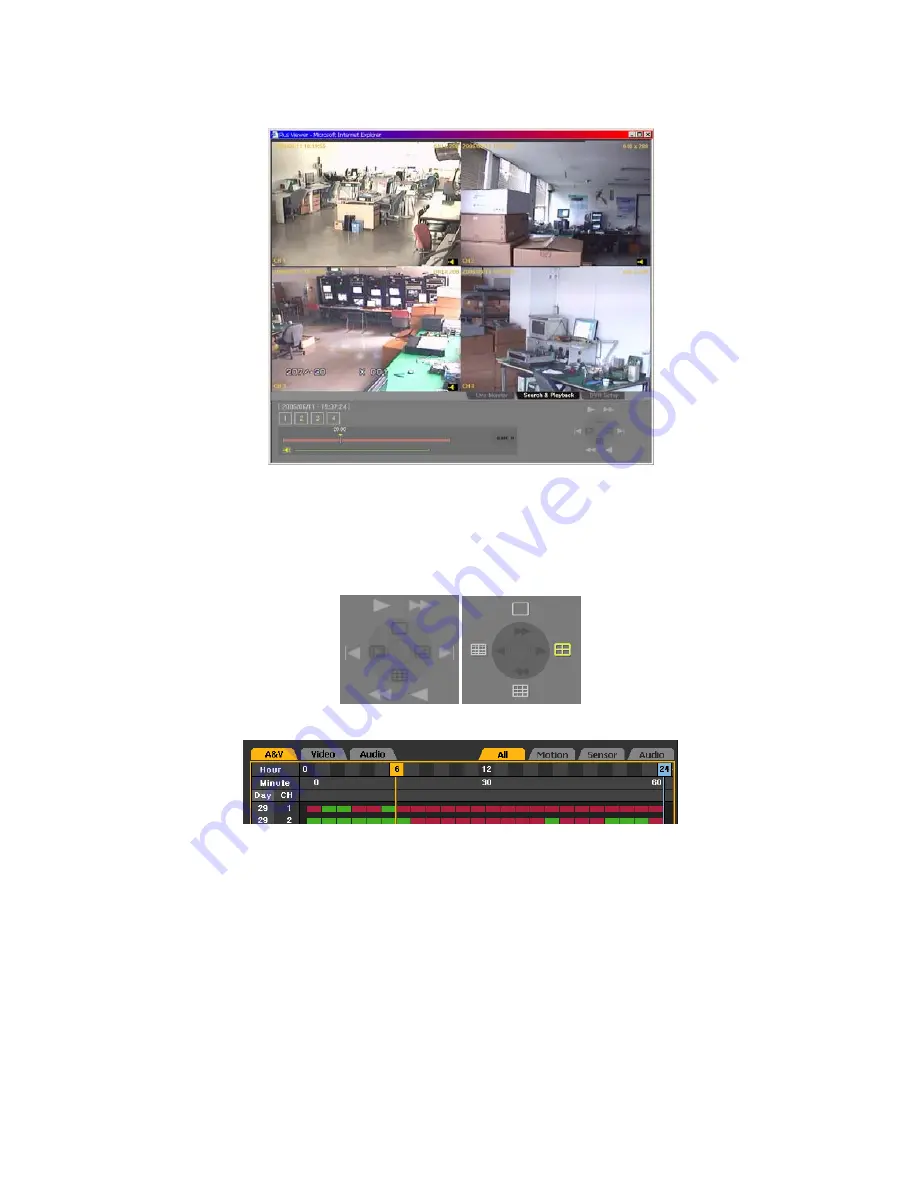
Below is the playback screen:


1-7-4. Playback Control 


The user can select the screen division and adjust the playback speed using the control at the 

lower right hand corner.


1-7-5. Screen Description 


 A & V – Displays all recorded files 


 Video – Displays only files with video 


 Audio – Displays only files with audio 


 All    – Displays all recorded videos on the list 


 Motion – Indicates the motion events 


 Sensor – Indicates the sensor events 


 Audio – Displays the audio events 


 General images displayed in green bars, and events, in red bars 


Summary of Contents for Workhorse 120-4

Page 1: ......

Page 2: ...s instructed in this manual All cables must be connected to grounded outlets 2 Install the DVR such that it is easy to disconnect the power cord 3 Do not use the DVR in water or in wet places may caus...

Page 3: ...emodel the product without permission IT WILL VOID YOUR WARRANTY 10 Incorrect system setup may cause undesirable effects 11 Shut down the system properly as instructed in this manual 12 The UPS power...

Page 4: ...ection 10 2 2 2 Adding a Hard Drive 13 2 2 3 CD RW DVD RW 17 3 Operation and Setup Tools 18 3 1 Front Buttons 18 3 2 Remote Control 19 3 3 Mouse 22 4 System Operation 23 4 1 Starting and Shutting down...

Page 5: ...ecording Setup 40 4 7 3 Viewing the Recording Status 40 4 7 4 Starting and Stopping Record All 41 4 7 5 Watermark 42 4 8 Search 43 4 8 1 Selecting Search Mode 43 4 8 2 Search Method 44 4 8 3 Selecting...

Page 6: ...ess 144 1 2 Description of the Basic Features 146 1 3 Audio 146 1 4 Color Adjust 147 1 5 DVR Network Setting 147 1 6 Viewing a Divided Screen 149 1 7 Search and Playback 150 1 7 2 Search Method 150 1...

Page 7: ...ding and playback at 120 100 NTSC PAL fps Resolution NTSC 320 240 640 240 640 480 PAL 320 288 640 288 640 576 Compression type MPEG4 video G 726 audio Backup Copy Ethernet USB2 0 Built in CD RW System...

Page 8: ...1 3 Components After unpacking the product check whether the following accessories are included 1 Basic parts 2 Optional parts DIO Sensor Relay Extension Module DIO Sensor Relay Extension Module Cabl...

Page 9: ...t is ON when the remote control is accessing the DVR 2 Network The green light is ON when the DVR is being accessed through the network 3 Backup The green light is ON when the DVR is making a backup 4...

Page 10: ...ade D SUB 9 pin 4 RS485 PTZ camera control cable connection RJ 11 6 pin 5 VGA VGA monitor connection D SUB 15 pin 6 TV CCTV monitor connection BNC 7 Video in Video camera connection BNC 8 Audio in Aud...

Page 11: ...monitor BNC or VGA 3 PTZ camera control cable RS485 4 Audio input output Audio input line in Audio output line out 5 LAN cable Ethernet 6 DIO sensor relay extended module DIO 1 The inputted video type...

Page 12: ...two audio input ports and one audio output port 3 DIO sensor relay extension module Connect the DIO sensor relay extension module to the DIO connector on the rear side using a D SUB 25 type extension...

Page 13: ...signal when closed normally Normal Open NO Closes in case of incoming signal when opened normally B Relay connection Relay output port Connect the alarm light or external alarm device to the relay out...

Page 14: ...ght The jumper setting method varies by manufacturer or model Refer to the jumper setting information marked on the front side of the hard drive Example Setting the jumpers for the western digital WD1...

Page 15: ...ng OFF the power shut down the system first Unscrew and open the upper case Unscrew the hard drive bay using a screwdriver and separate the hard drive bay from the body Insert the hard drives into the...

Page 16: ...ctor 0 Connector 1 2 Installing two HDDs System Master Slave Primary Master E IDE Connector 0 Connector 1 2 Connecting two hard drive connection cables 1 Installing three HDDs System Master Slave Prim...

Page 17: ...screws Close the upper case and fasten the screws Turn the power ON and start the system After adding a hard drive select Main Setup Storage Device Local 3 Manage Local Storage Device For more informa...

Page 18: ...se Screw in the CD RW DVD RW on the front CD RW DVD RW bay Connect the power cord of the CD RW DVD RW and the E IDE cable to the corresponding ports Note Before connecting the E IDE cable to the slave...

Page 19: ...The red light is ON when an alarm is triggered 6 CD RW DVD RW CD RW DVD RW installation slot 7 Numeric buttons Numeric buttons 8 USB External backup device or USB mouse connection 9 Remote control se...

Page 20: ...set up the recording recording schedule and system APP SETUP APP setup Used to set up the PTZ and network PTZ PTZ Changes the PTZ camera control mode SEARCH Search Searches recorded images Move Moves...

Page 21: ...Used to view the system logs RECORD Record Used to record all channels or stop recording all channels BACKUP Backup Used to back up the stored video data in Search mode STATUS Status Used to view syst...

Page 22: ...21 FNC 2 4 FNC 2 4...

Page 23: ...ntrol and touch screen 2 Main setup Used to set up the recording recording schedule and system 3 Additional setup Used to set up the PTZ and network 4 PTZ Changes the PTZ camera control mode 5 Search...

Page 24: ...d is inputted the system is initialized and the initial screen appears After the system is initialized and started the video of all connected channels is displayed Note The password may contain up to...

Page 25: ...nt part blink and a warning sound is generated for approximately 20 seconds before the system shuts down If an incorrect password is inputted a warning message is displayed followed by the previous sc...

Page 26: ...corded video Download network file Network access and file download Main setup Additional setup Recording setup Recording schedule System Storage device NTP Advanced setting PTZ camera Network setup N...

Page 27: ...the password using the numeric buttons on the remote control The default password of the local administrator is 00000 Click the ID selection box and press the arrow ST buttons on the remote control or...

Page 28: ...ess 3 4 to view the video of Channel No 3 5 6 and to view the video of Channel No 4 press the 7 8 button 4 divided screen 1 screen Press the Left button on the remote control and short press the 9 0 b...

Page 29: ...ct the login account input the password using the numeric buttons on the remote control and select OK The default password of the local administrator is 00000 Go to the ID selection box and press the...

Page 30: ...he desired channel Afterward click the Select button On the channel selection box select and save the audio channel An audio icon is then displayed on the real time monitoring screen 4 4 2 Changing th...

Page 31: ...with the voice set on the real time monitoring window as shown below Change the window using the arrow STW X buttons and click the Select button to select an audio channel The real time monitoring scr...

Page 32: ...ion window Activation mode The channel selection window can be moved At this time the border of the channel screen is displayed in orange Selection mode The channel is selected At this time the border...

Page 33: ...mware version Firmware version on the front part 6 Video mode Video mode NTSC PAL 7 HDD information Hard drive Total space Total space Used space Used space Free space Remaining space Start day Record...

Page 34: ...on again 4 5 3 Adjusting the Contrast Press the Status button to shift to contrast control mode as shown below Select the channel on the monitoring screen to adjust the contrast Adjust the contrast of...

Page 35: ...5 5 TV Control Use TV Control to adjust the images displayed on the CCTV monitor by moving the CCTV monitor screen up down right or left as shown below Press the Status button to shift to TV control...

Page 36: ...own below select ON or OFF using the arrow W X buttons and press the Select button 4 5 8 Controlling the Screen Border Used to display hide the screen border and to control the border form thickness t...

Page 37: ...lines Width 2 4 Sets the width Transparency 10 25 50 75 100 Sets the transparency Color Black White Red Green Blue Sets the color of the border 4 5 9 Reset Resets the Status settings Press the Status...

Page 38: ...t Logs related to recording such as detection of motion sensor and sound 3 Network Logs related to network operations such as network login network logout and network live 4 Failure Logs related to op...

Page 39: ...s the time On the other hand a blue triangular icon is displayed on the date each time a change is made in the date on the calendar window Otherwise a red triangular icon is displayed on the unchanged...

Page 40: ...rded video screen press the Play button 0 min currently displayed video s position Go to video of desired minute by moving the red arrow Recorded video exists up to this minute Play speed control Step...

Page 41: ...event frame setting in case of input signal from an external sensor Sound Recording is done based on the event frame setting in case sound is detected 4 7 2 Recording Setup Select Main Setup Recording...

Page 42: ...status Network connected Network disconnected 4 7 4 Starting and Stopping Record All To start or stop All Recordings press the Record button on the remote control or on the Record menu in real time m...

Page 43: ...splayed on the OSD as shown below 4 7 5 Watermark This system uses Watermark technology to detect video forgery and alteration Fragile Watermark technology is used Fragile Watermark technology detects...

Page 44: ...arch menu The initial menus of the search mode are then displayed as shown below Activation mode and Selection mode Activation mode The field can be moved or selected on the OSD menu At this time the...

Page 45: ...hes the video of one channel for the multiple time zones of one date 4 8 3 Selecting the Search Tool Before selecting the date go to the search tool selection box by pressing the TAB button Afterward...

Page 46: ...5 A Multi channel Select the time using the arrow ST buttons B Multi time Select the time and channel using the arrow W XST buttons C Multi day Select the time and channel using the arrow W XST button...

Page 47: ...to time change 1 Changing the time by selecting Main Setup NTP 2 Date and Time causes the data folder to be updated and subsequently displayed in blue on the file list 2 Selecting the changed time cau...

Page 48: ...recorded Yellow Sound is recorded Light blue Shows that recording was done before the time was changed Set the time by using the arrow W X or numeric buttons or moving the time indicator and press the...

Page 49: ...X and numeric buttons and click the Select button Input numbers that are less than 10 in two digits using the numeric buttons e g 08 for 8 and 09 for 9 4 8 5 Multi hour Searches the video of one chann...

Page 50: ...nnel is then displayed in a minute unit bar graph Define the starting point of the search time using the arrow STW X and numeric buttons and click the Select button Input numbers that are less than 10...

Page 51: ...ow STW X buttons 3 Minute The recorded video of the selected channel is then displayed in a minute unit bar graph Define the starting point of the search time by using the arrow STW X and numeric butt...

Page 52: ...allowed To search and play however either Multi channel or Multi date or Multi hour mode may be used 1 Search In Search mode select Multi channel Multi date or Multi hour Set the play date time channe...

Page 53: ...52 2 Multi time 3 Multi day...

Page 54: ...n Multi channel mode The user cannot play the data recorded before the time change 4 9 2 Playing and Controlling the Play Speed 1 Playing In Play mode press the Search button The video is then played...

Page 55: ...ct sub screen 4 sub screens To view the video of a certain channel select the desired channel by pressing the numeric buttons Pressing the button on the remote control enables changing the screen To v...

Page 56: ...e 3 4 front button On the 4 divided screen double click the video to view it on full screen Double click any area on the Enlarge window to convert into a 4 divided screen 9 divided screen 2 screens To...

Page 57: ...played for the channel with the voice recording set together with an orange colored activation window Go to another window using the arrow STW X buttons and press the Select button The recorded audio...

Page 58: ...e to block the sound of the selected channel In Play mode press the Mute button on the remote control Drag the cursor to the upper right corner On the popup menu select Mute An audio icon is then disp...

Page 59: ...is then changed as shown below 4 9 6 Smart Search Use Smart Search to search the motion of objects in a certain zone quickly In Play mode select the Search button Drag the cursor to the upper right co...

Page 60: ...59 Select the channel to be searched...

Page 61: ...one press the Select button The user can set up to four search zones Right click the green zone or press the Main Setup button on the remote control to set the motion degree There are five motion degr...

Page 62: ...earch zone where motion is detected turns green The user can play the video searched via Smart Search using the following search buttons 4 9 7 Digital Zoom in The user can enlarge a certain part while...

Page 63: ...ng the arrow W X buttons and press the Select button Selecting the Zoom button to zoom in out the video from X2 X3 up to X causes the selected channel to be displayed The user can select another chann...

Page 64: ...with USB2 0 interface an external CD RW DVD RW or any other storage device to the USB2 0 port on the front side Refer to the appendix for the list of supported external devices Select Search Multi Cha...

Page 65: ...W X buttons or pressing the Select button Note To back up a channel or cancel backup go to the backup channel by using the arrow buttons and pressing the Select button The backup channel is then displ...

Page 66: ...ponding backup information is then displayed Check the backup information and click Yes on the message window as shown below If the backup storage device has not been formatted or in case the storage...

Page 67: ...sage appears After backup is completed press the Select button on the message window as shown below Once the following message appears separate the backup device from the USB 2 0 port on the front sid...

Page 68: ...ing mode press the PTZ button on the remote control An icon is then displayed on the channel with the PTZ camera set together with the channel selection window as shown below If the PTZ camera is not...

Page 69: ...in using the arrow buttons To select another screen in zoom in out mode press the right left TAB button 3 Focus control In zoom in out mode press the PTZ button on the remote control A toolbar is the...

Page 70: ...us settings of the PTZ camera For more information on setting the Tour feature go to Additional Setup PTZ Setup Tour Once the Tour feature is enabled No 9 or No 0 on the OSD is displayed in blue in ho...

Page 71: ...control or go to the Main Setup menu on the real time monitoring screen The login window is then displayed as shown below Select the login account and input the password using the numeric buttons on...

Page 72: ...g and events 1 Selecting the recording setup menu mode Recording Setup supports two modes data mode and channel mode A Selecting the menu method Navigate by pressing the TAB and arrow W X buttons on t...

Page 73: ...based on the data profile as shown below Channel mode The user can set the data of Channel Nos 1 4 based on the four channel groups as shown below 2 Saving the recording setting Set each menu in Recor...

Page 74: ...n The user can select multiple data from Data 1 to Data 4 The selected data are then displayed in green and others in blue C Saving on the message window Closing the window without saving the new reco...

Page 75: ...n Caps lock Used to shift to upper case BS Backspace used to delete Space Used to insert space Cancel Used to cancel the save Save and exit Used to save and exit After inputting the data go to Save an...

Page 76: ...channel port and to set video input On the Recording Setup Data 1 4 Title menu go to the channel using the arrow STW X buttons and press the Select button To set all channels at the same time go to T...

Page 77: ...ns Resolution by video type Type Resolution NTSC PAL CIF 320x240 320x288 Field 640x240 640x288 Full 640x480 640x576 B Recorded video quality Sets the quality of the recorded video On the Recording Set...

Page 78: ...ntinuous Recording done based on the normal frame setting Motion Recording done based on the event frame setting in case motion is detected Sensor Recording done based on the event frame setting in ca...

Page 79: ...ormal Sets the recording frame rate for Automatic and Continuous recording Event Sets the recording frame rate for Automatic Motion Sensor and Sound recording Note Maximum recording frame by resolutio...

Page 80: ...arrow ST and Select buttons 7 Event setup A Motion Used to detect motion Detection settings include Full Partial and OFF The default setting is OFF The full video of a certain channel is displayed as...

Page 81: ...he Recording Setup Data 1 4 Event Motion menu go to the channel using the arrow STW X buttons and press the Select button To set all channels at the same time go to Motion and select the Main Setup bu...

Page 82: ...displayed in green The Select button may be used for toggling OFF Disables the detection of motions in the video Setting the motion detection sensitivity On the Recording Setup Data 1 4 Event Motion...

Page 83: ...ecting input from an external sensor compatible with the system The user can set up to four external sensors Once signal input is detected the video of the corresponding channel is recorded Sensor set...

Page 84: ...signal when opened normally C Sound Defines the settings for detecting audio input from an external device compatible with the system The user can set the audio input for two external devices compatib...

Page 85: ...p button Afterward right click Sound On the selection box set the audio channel using the arrow ST and Select buttons D Post This DVR does not support Prerecord time Sets the recording time upon the o...

Page 86: ...larms through the buzzer mail or relay in case of an event A Buzzer Used to sound the buzzer in the system in case of an event On the Recording Setup Data 1 4 Generate Alarm Buzzer menu go to the chan...

Page 87: ...larm or an event On the Recording Setup Data 1 4 Generate Alarm Mail menu go to the channel using the arrow STW X buttons and press the Select button On the selection box set an event to send an email...

Page 88: ...larm Relay menu go to the channel using the arrow STW X buttons and press the Select button On the selection box set an event to run the alarm device using the arrow ST and Select buttons Multiple eve...

Page 89: ...88 Relay type setting On the Recording Setup Data 1 4 Generate Alarm Relay menu go to the channel using the arrow STW X buttons and select the Main Setup button Afterward right click Relay...

Page 90: ...ancel Exits without saving the setting Reset Initializes the setting 1 Selecting the Recording Schedule menu In Main Setup mode go to Recording Schedule and click the Select button 2 Recording schedul...

Page 91: ...et all rows after the selected time press the Select button or double click the corresponding button on the menu On the selection box go to the data using the arrow ST buttons and press the Select but...

Page 92: ...bers that are less than 10 in two digits using the numeric buttons e g 01 for 1 and 02 for 2 Select the time to set the data a To set only one column of the selected time press the Main Setup button o...

Page 93: ...lect button Data are set based on the buttons pressed during time selection a Pressing the Main Setup button causes the data to be set only for the column with the selected time b Clicking the Select...

Page 94: ...ay list The list of all defined holidays is displayed 15 holidays are displayed on each page the rest is displayed on the next pages C Holiday information Detailed information of the selected date is...

Page 95: ...On the Add Holiday window go to the date using the arrow STW X and Select buttons and press the Select button After setting the holiday press the ESC button followed by the Save button at the bottom o...

Page 96: ...em 6 Date display type Used to set the date format 7 Users Used to register add or delete users 8 Buzzer Turns the alarm sound feature ON OFF 9 Alarm Duration Sets the alarm generation time in seconds...

Page 97: ...t button 3 Menu Time Out If no input is made on the System Setup menu using the front buttons remote control or mouse the system automatically shifts to real time monitoring mode On the System menu go...

Page 98: ...ting the data go to Save and Exit using the Tab or arrow ST buttons and press the Select button 4 Modem Baud rate Sets the modem transmission rate On the System menu go to 3 Modem Baud Rate using the...

Page 99: ...to save and exit After inputting the data go to Save and Exit using the Tab or arrow ST buttons and press the Select button The system name may contain up to 20 alphanumeric characters 6 Remote ID Se...

Page 100: ...and press the Select button After setting the remote control ID of the DVR apply the new setting Select the ID button and enter the two digit remote control ID Afterward select the ID button again To...

Page 101: ...grade Remote upgrade A Modifying user information On the System menu go to 6 User Modify using the arrow ST buttons and press the Select button On the selection box select a user using the arrow ST an...

Page 102: ...d the following message is displayed W To go back to the previous menu press the Select button On the user ID input window enter the user ID using the numeric buttons on the remote control or the arro...

Page 103: ...elete Cancel Used to cancel the save Save and exit Used to save and exit After inputting the data go to Save and Exit using the Tab or arrow ST buttons and press the Select button After setting the us...

Page 104: ...and Select buttons An alarm is sounded through the buzzer inside the system in case of HDD Failure Backup Failure Network Failure Fan Failure Power Failure or Signal Loss 10 Alarm Duration Sets the al...

Page 105: ...nnected from the port while the upgrade file is being copied the DVR system may not automatically recognize the file Upgrading cannot proceed if no HDD is installed Connect the storage device containi...

Page 106: ...us Product Information 3 Software Version 12 Factory Setup On the System menu go to 11 Factory Setup using the arrow ST buttons and press the Select button To reset click the Yes button All settings e...

Page 107: ...System menu save the new configuration before exiting the menu After completing the system configuration go to Save by selecting the Tab button and press the Select button Save Saves the new configura...

Page 108: ...buttons To apply the new setting defined in the Storage Device menu save the new setting Update Used to read local storage device management information again Save Saves the setting Cancel Exits witho...

Page 109: ...ive space files starting from the oldest ones are overwritten Off Once the hard drive space is used up recording stops 4 Selecting the Local Storage Management menu On the Storage Device menu go to 3...

Page 110: ...re information see the warning below Fault Not connected to the DVR possible hardware damage in this state the storage device cannot operate 1 Fault state The storage device is damaged and unable to f...

Page 111: ...rage Device menu go to Storage Device Local using the arrow ST buttons The following window is then displayed together with information on the newly installed drive Select a model using the arrow ST a...

Page 112: ...state are then displayed as shown below 8 Operation of the local storage device The user can select any valid storage device using the arrow ST buttons Select a storage device using the Select button...

Page 113: ...NAS using the arrow ST buttons and press the Select button On the selection box select ON or OFF using the arrow ST and Select buttons Selecting ON or Test causes a test to run as shown below 3 ID Go...

Page 114: ...Select button 4 Password Go to the 3 Password menu using the arrow ST buttons and press the Select button On the input window enter the password using the arrow STW X and Select buttons Caps lock Use...

Page 115: ...delete Space Used to insert space Cancel Used to cancel the save Save and exit Used to save and exit After inputting the data go to Save and Exit using the arrow STW X or Tab buttons and save the set...

Page 116: ...w ST and Select buttons 9 Min Spare Space Go to the 8 Min Spare Space menu using the arrow ST buttons and press the Select button On the input window enter the minimum space using the arrow STW X and...

Page 117: ...116 On the selection box select ON or OFF using the arrow ST and Select buttons...

Page 118: ...rver fails synchronization with the RTC ensues 2 Synchronization with the DVR Time Server The DTS server runs in Workhorse 120 4 time is synchronized by the hour Workhorse 120 4 DTS clients referring...

Page 119: ...n box shift to NTP mode using the arrow ST and Select buttons OFF NTP is not used Server The DVR time server is used Client DTS client is used and server time synchronized B Server type Settings may b...

Page 120: ...n On the selection box set the server URL using the arrow ST and Select buttons The user can input the IP only when the server type is DVR For the NTP server Automatic IP or URL should be selected Aut...

Page 121: ...ging the date and time using the arrow ST buttons press Select The following message is then displayed and the system time changed 4 Time zone Used to set the standard time A Daylight savings time Use...

Page 122: ...Advanced menu Select Main Setup and Advanced Advanced menu configuration The user can set each channel in detail as shown below data may be set for each channel e g from Channel No 1 to Channel No 4...

Page 123: ...TW X and Select buttons as shown below BS Backspace used to delete Cancel Used to cancel Save and exit Used to save and exit After inputting the data go to Save and Exit using the arrow STW X or Tab b...

Page 124: ...sing On the V Anti aliasing menu as shown below press the Select button F Peaking On the Peaking menu as shown below press the Select button G C Y cording On the C Y Cording menu as shown below press...

Page 125: ...the original image Quad Maximum bit rate This refers to the maximum size unit for the streaming of moving images H anti aliasing This is used to set the horizontal anti aliasing In most cases 4MHz is...

Page 126: ...l Setup On the real time monitoring screen select the Additional Setup button on the remote control The login window is then displayed as shown below Select the login account enter the password using...

Page 127: ...l cable type RS 485 Transmission rate Communication speed must be the same as the communication speed specified in the manual for the PTZ Preset maintenance time Interval between the Preset as defined...

Page 128: ...facturer or model See the camera manual for reference On the PTZ Setup menu select the Camera ID sub menu and go to the channel using the arrow STW X buttons Afterward press the Select button On the s...

Page 129: ...the baud rate using the arrow ST and Select buttons 5 Preset time setting Preset Used to move the PTZ camera up down right and left to zoom in the image and to control the focus to save the new setti...

Page 130: ...terval between 5 and 60 seconds Example Tour feature when Tour 1 and Tour 2 are set as follows When 9 is pressed in PTZ mode Numbers are selected in the following order 1 7 5 6 Selecting 9 again disab...

Page 131: ...k Setup menu In Additional Setup mode go to Network and press the Select button 2 Ethernet Uses a fixed IP in the local area network environment On the Network Setup menu go to Ethernet using the arro...

Page 132: ...button b Go to BS using the Tab or arrow ST buttons c Delete only the incorrect value using the Select button d Enter the new value using the numeric buttons on the remote control or the arrow STW X...

Page 133: ...and press the Select button C Subnet mask setting On the Ethernet Setup menu go to the subnet mask input field using the arrow ST buttons and press the Select button On the input window enter the subn...

Page 134: ...ic buttons on the remote control or the arrow STW X and Select buttons BS Backspace used to delete Cancel Used to cancel the save Save and exit Used to save and exit After inputting the data go to Sav...

Page 135: ...s and press the Select button F Auxiliary DNS setting On the Ethernet Setup menu go to the auxiliary DNS input field using the arrow ST buttons and press the Select button On the input window enter th...

Page 136: ...N 1 1 Used when the remote access software is connected to the DVR at a ratio of 1 1 On the Network Setup menu go to PSTN using the arrow W X buttons and press the Select button To select 1 2 or3 use...

Page 137: ...ISDN ISP Used in the ISP provided communication environment On the Network Setup menu go to PSTN using the arrow W X buttons and press the Select button Use the Tab or arrow W X buttons to navigate be...

Page 138: ...atic ADSL access or a dynamic IP On the Network Setup menu go to Cable using the arrow W X buttons and press the Select button To select 1 2 or 3 use the Tab button For others use the arrow W X button...

Page 139: ...cation type ADSL environment On the Network Setup menu go to ADSL using the arrow W X buttons and press the Select button To select 1 2 or 3 use the Tab button For others use the arrow W X buttons Ent...

Page 140: ...ect Main Setup Data Setup and enable Call or Mail Alarm On the Network Setup menu go to Alarm using the arrow W X buttons and press the Select button To select 1 2 or 3 use the Tab button For others u...

Page 141: ...s between 2000 and 2007 a randomly chosen value may be used depending on the network environment e g firewall On the Network Setup menu go to Port using the arrow W X buttons and press the Select butt...

Page 142: ...remier Series provide a dynamic DNS to ensure URL access in a dynamic IP environment Its built in web server feature enables remotely monitoring images through the Internet anytime Go to DDNS using th...

Page 143: ...s password registered in the DDNS server Enter the IP address of the DDNS server The default IP address of the DDNS server is 211 117 45 25 Set the default port of the DDNS server The default port of...

Page 144: ...143...

Page 145: ...ccess the DVR system through the web Enter the IP of the DVR system on the address field of the web browser The ID and password are the same as those of the user account set in the DVR system After lo...

Page 146: ...145 Click Install on the window as shown below After installing ActiveX the user can use Plus Viewer on the web browser...

Page 147: ...auses the channel to be selected and the border of the corresponding screen to be displayed in a different color the figure above shows the case where in Channel No 1 is selected The user can also vie...

Page 148: ...djust Click Color Adjust to adjust the display colors After adjusting the display colors click Close to save the setting and close the window 1 5 DVR Network Setting To view the DVR setting click DVR...

Page 149: ...ution Used to adjust the resolution the lower the resolution the higher the transmission speed CIF Field Full Picture quality Used to adjust the picture quality the higher the picture quality the high...

Page 150: ...nel video is displayed on the monitoring window the user can view the divided screen by clicking the Division Mode button To view one channel on full screen double click the channel To return to divis...

Page 151: ...ottom 1 7 2 Search Method Search Displays the recorded video in the form of an hour minute bar graph Search Displays the recorded video in the form of a file list 1 7 3 Search and Play On the search w...

Page 152: ...151 Select the date and time and click The following screen is then displayed Select the minute and click The video is then played To go back to the previous screen click...

Page 153: ...right hand corner 1 7 5 Screen Description A V Displays all recorded files Video Displays only files with video Audio Displays only files with audio All Displays all recorded videos on the list Motion...

Page 154: ...es the following screen to be displayed Change the system setup on the DVR setup screen by clicking System Setup For more information on system setup see Chapter 5 System Setup After changing the syst...

Page 155: ...Viewer When recorded data is backed up from the DVR system a new folder is created in the backup device including QuickViewer exe and mwmp4dec dll files The user can run Quick Viewer by executing Quic...

Page 156: ...An open file dialog box then appears as shown below Select the rms file of the channel to be played 2 2 Description of Buttons Fast backward play Backward play Previous frame Next frame Forward play...

Page 157: ...156 2 3 Version Information To check the version of Quick Viewer click Help About...

Page 158: ...157 Workhorse 120 4 A P P E N D I X A P P E N D I X 157 1 PTZ Camera Protocol 158 2 Recommended HDD 158 3 Recommended USB 2 0 Device 159 Memory Stick 159 2 5 Portable USB HDD 159 CD RW DVD RW 159...

Page 159: ...M 7200 7200 2 Seagate SEAGATE BARRACUDA 7200 9 ST3120213A SEAGATE BARRACUDA 7200 7 ST3160023A SEAGATE BARRACUDA 7200 7 ST3200822A SEAGATE BARRACUDA 7200 7 ST3200827A SEAGATE BARRACUDA 7200 9 ST3250823...

Page 160: ...LG Xtick USB Drive 256MB 4 AL Tech ANYDRIVE mini USB 256MB 5 Kingston DataTraveler USB FLASH DRIVE 256MB 6 Sarotech FLEX FD 03U1 128MB 8 Sandrive Cruzer Mini 128M 10 Samsung PLEOMAX 128MB 11 Sony Micr...

Page 161: ...160...

Reviews: