


T811-CM AP Installation Guide, 800-71436-001 Rev A
7
About This Installation Guide
1
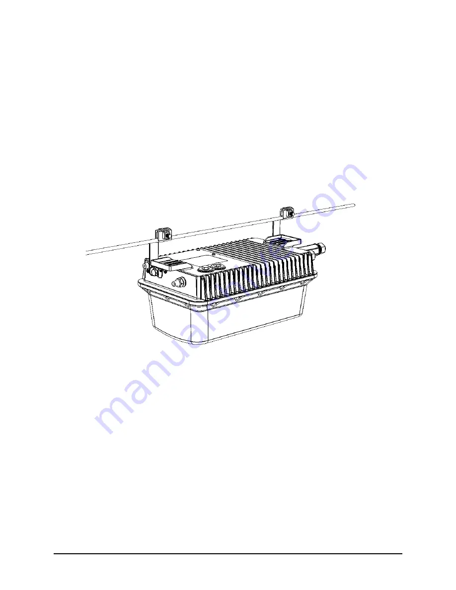
This
Installation Guide
provides information on how to set up the Ruckus Wireless T811-CM (model
901-T811-CM-US31) strand mount access point (AP) with integrated cable modem (CM) on your
network. Topics covered in this guide include basic configuration, operation and mounting. The rest
of this document refers to the strand mount access point with integrated cable modem as the
T811-CM
.
This guide is intended for use by those installing and configuring network equipment. Consequently,
it assumes a basic working knowledge of local area networking, cable modem configuration, wireless
networking, and wireless devices.
Figure 1. Typical T811-CM mounted on a cable strand
Summary of Contents for T811-CM
Page 2: ...2 TT811 CM AP Installation Guide 800 71436 001 Rev A ...
Page 4: ...4 TT811 CM AP Installation Guide 800 71436 001 Rev A ...
Page 42: ...T811 CM AP Installation Guide 800 71436 001 Rev A 40 ...
Page 46: ...T811 CM AP Installation Guide 800 71436 001 Rev A 44 Weight ...
Page 52: ...T811 CM AP Installation Guide 800 71436 001 Rev A 50 ...
Page 53: ...T811 CM AP Installation Guide 800 71436 001 Rev A 51 ...


