


21
4.2
Working with the RTS SIP-ISDN
In the next chapters basic functions like establishing a connection, dropping a connec-
tion, accepting calls etc. are decribed in detail.
4.2.1
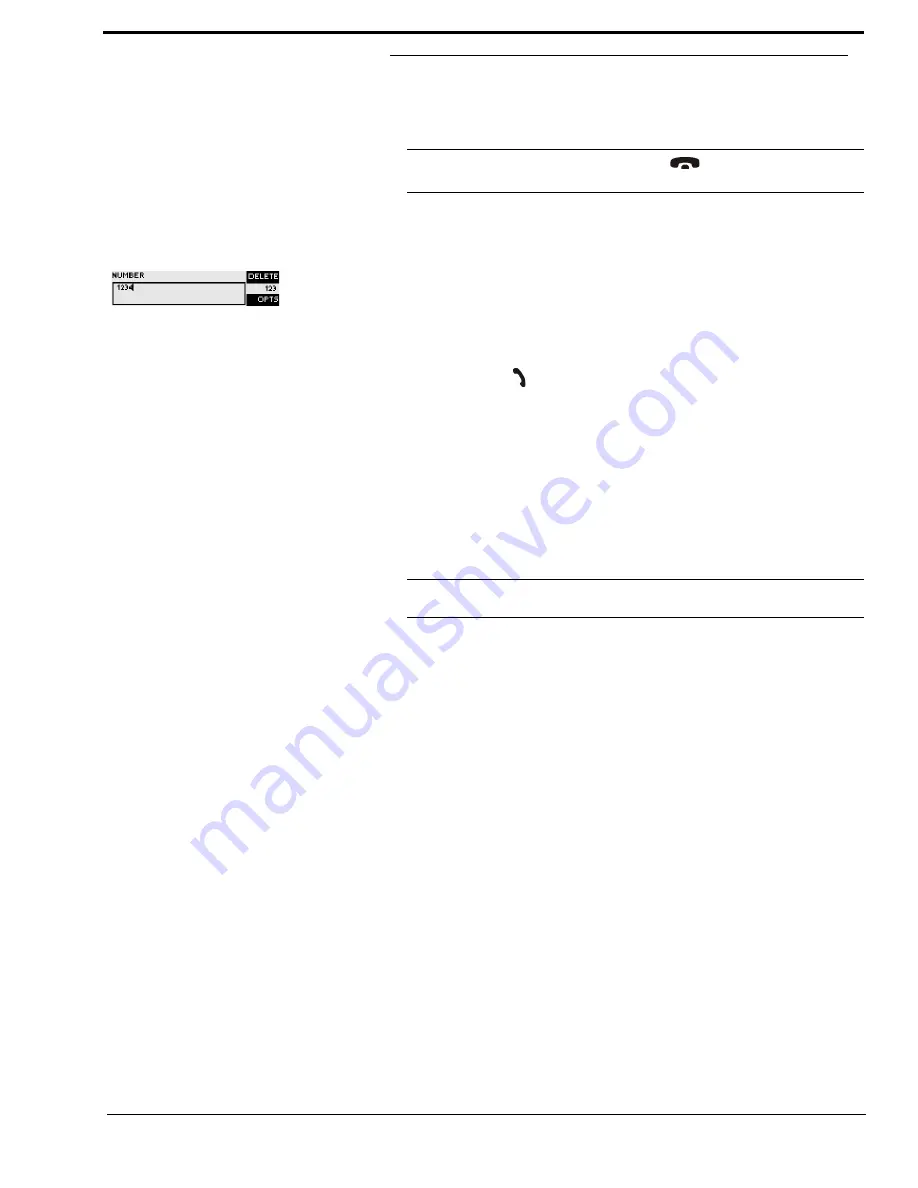
Calling a partner
From the main menu just enter the phone number using the keys
0...9
. The input field for
the phone number is displayed automatically after entering the first cypher.
With the softkey
misentries can be corrected.
The connection is established after the entry of the phone number by pressing the tele-
phone receiver button
.
Under the softkey
(Options) the entered phone number can be saved in the phone
book see CHAPTER 4.3.2, Page 23) or stored as Quick Dial Number see CHAPTER
4.3.2, Page 23).
4.2.2
The Status Display - Operation during a connection
After the telephone receiver button is pressed the partner is called and the status window
is displayed automatically.
During a stereo connection the number of the connected B channels is displayed to the
left of the level indication.
In the
ISDN
operating mode the window is split if two independent connections have
been established.
To switch between the two connections, please press the
key (
#
). The name of the
selected channel is displayed inversely.
An outgoing call is signalised by
. The dialled number (or the name if a
phone book entry is selected) is displayed in the first line.
When the connection is established the level indication for the incoming signal(
R
eceive)
and for the outgoing signal(
T
ransmit) is displayed.
With the use of the softkey
the displayed phone number can be stored and it is also
possible to directly switch to the phone book.
NOTICE
If you are not in the main menu please press the
button first.
From the main menu you reach the status window via the
TIP
The status window can always be reached by pressing the
OK
button.
Summary of Contents for SIP-ISDN
Page 6: ......
Page 12: ...12...
Page 29: ...29 FIG 10 TEN MOST RECENTLY DIALLED NUMBERS...
Page 62: ...62...
Page 66: ...66 FIG 49 S0 MONITOR LAYER 3...
Page 68: ...68 A1 1 System Settings...
Page 69: ...69 A1 2 Operation Settingss...
Page 70: ...70 A1 3 Presets...
Page 72: ...72 A1 5 Login...
Page 73: ...73 A1 6 Names...
Page 74: ...74...
Page 77: ...77 A2 4 Data Control Adapter Cable...
Page 78: ...78...
Page 82: ...82...
Page 84: ...84...
Page 91: ...91 A 6 T E C H N I C A L D A T A R T S S I P I S D N...
Page 92: ...92...
Page 96: ...96...
Page 97: ...97 A 9 S E R V I C E I N F O R M A T I O N...
Page 98: ...98...