Touchscreen Control Panel
It’s Under Control
®
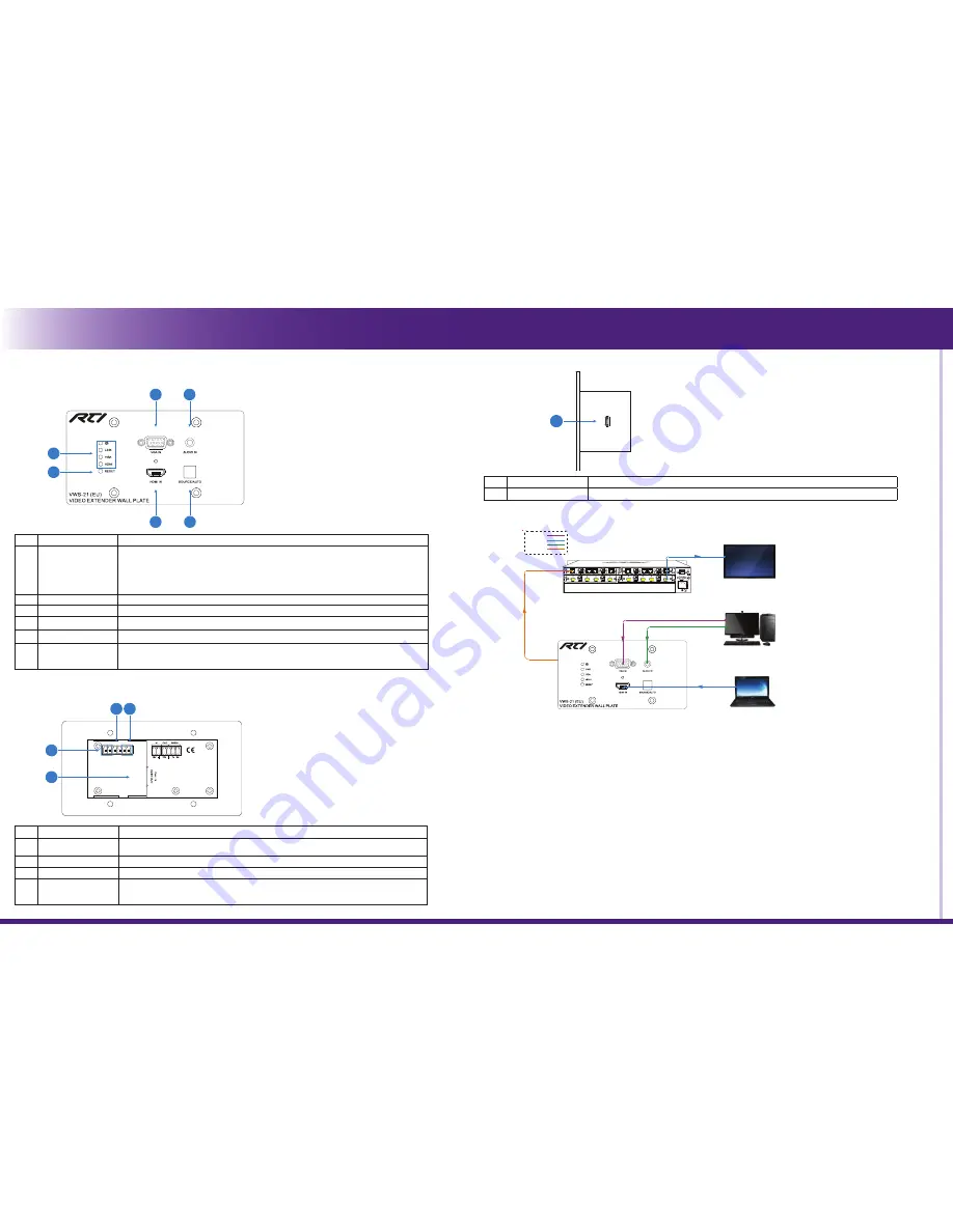
FRONT PANEL DESCRIPTION
Installation & Operation
3
6
5
4
1
2
CONNECTION DIAGRAM
RS232
TCP/IP CONTROL
Laptop
Cat 5e/6A
PC
HDBaeT Receiver/Matrix
Wallplate HDBaeT Transmitter
Projector/Flat Screen Display
HDMI:
VGA:
HDBaseT:
Audio:
REAR PANEL DESCRIPTION
3 4
1
2
No.
Name
Function
1
HDBT OUT/PoH IN
RJ45 HDBaseT output port to connect to the HDBaseT input port of the compatible receiver by
CATx cable.
2
12V Power In
Power port to connect the 12V DC power adapter.
3
12V Power Out
2-pole captive screw connector to connect a compatible device which needs to be powered.
4
RS-232
3-pole captive screw connector for RS-232 pass-through control.
It can be connected with control system (Use a 3-pole captive to 9 pin female D connector) , or
connected with the device which needs to be controlled.
Press and hold the
SOURCE/AUTO
button for 3 seconds. When the button lights up green the VWS-21T is in AUTO mode. This
mode automatically selects the last video source connected to the VWS-21T and outputs it to the display. Press and hold again for
approximately 3 seconds, the light will go out, and the device will be in Manual mode which will allow the user to momentarily press
the button to toggle between the two sources.
BUTTON CONTROL
No.
Name
Function
1
Indicators
•
POWER: Turns red when power on.
•
LINK: Turns blue when the transmitter/matrix and the receiver are connected successfully.
•
VGA: Turns orange when the VGA input port is connected to a source device, and it will
turns blue once the device is selected as input source.
•
HDMI: Turns orange when the HDMI input port is connected to a source device, and it will
turns blue once the device is selected as input source.
2
RESET
Press the button to reboot this unit.
3
VGA IN
DB9 jack for connection to a VGA source device.
4
AUDIO IN
3.5mm jack to connect an audio source device to provide audio for the VGA input video.
5
HDMI IN
Type-A HDMI connector to connect an HDMI source device.
6
SOURCE/AUTO
•
Press the button to switch input signal manually between HDMI and VGA sources.
•
Press and hold the button at least 3 seconds to enter auto-switching mode. Press and hold
again can exit.
REAR PANEL DESCRIPTION
FIR
M
W
A
R
E
1
No.
Name
Function
1
FIRMWARE
Micro-USB port for firmware upgrade.
To control the VWS-21T using serial communication from a control system, wire the RS-232 output of the control system to the RS-232
connector.
•
Baud rate: 9600
•
Data bit: 8
•
Stop bit: 1
•
Parity bit: none
RS-232 CONTROL
INSTALLATION
Please visit the RTI dealer portal (www.rticorp.com/dealer) for additional instructions and specifications.
NOTE: Features and specifications subject to change without notice.