RTI Slit Camera, User Manual
The RTI Slit Camera is a high-quality imaging device designed for precision photography. Capture detailed images with ease using this innovative camera. Ensure optimal use by downloading the free user manual from manualshive.com. Get your manual today and unleash the full potential of your RTI Slit Camera.
Share
Download


Reviews:
No comments
Related manuals for Slit Camera

R50
Brand: Kaiser Baas Pages: 2

Lumix H-FSA14140
Brand: Panasonic Pages: 26

Lumix H-HS12035
Brand: Panasonic Pages: 26

HFS1442A
Brand: Panasonic Pages: 26

H-NS043
Brand: Panasonic Pages: 26

H-H025
Brand: Panasonic Pages: 2

H-FS35100
Brand: Panasonic Pages: 2

H-FS045200 - Lumix Telephoto Zoom Lens
Brand: Panasonic Pages: 26

ET-D3LEW10
Brand: Panasonic Pages: 18

FL500 - DMW - Hot-shoe clip-on Flash
Brand: Panasonic Pages: 44

S2
Brand: Zenza Bronica Pages: 29
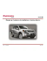
XUV500
Brand: Mahindra Pages: 12

Lumix DMC-FX80
Brand: Panasonic Pages: 20

LUMIX DMC-FX50
Brand: Panasonic Pages: 7

HX-A500
Brand: Panasonic Pages: 40

GP-MF622E
Brand: Panasonic Pages: 15

Lumix DMC-FZ300
Brand: Panasonic Pages: 72

Lumix DMC-FS15
Brand: Panasonic Pages: 24


