background image

1

Content

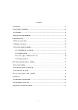
1. Introduction ....................................................................................................................... 2

2. Characteristic indicators ................................................................................................... 2

2.1 Features ......................................................................................................................2

2.2 Electrical Specifications ..............................................................................................3

3 ports and wiring ................................................................................................................. 3

3.1 Power connection ....................................................................................................... 4

3.2 Motor connection ........................................................................................................ 5

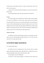
3.3 Control signal connection ........................................................................................... 5

3.3.1 Pulse & Direction Signal ...................................................................................... 5

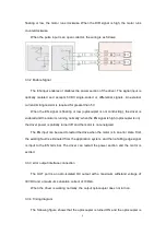
3.3.2 Enable Signal .......................................................................................................6

3.3.3 error output interface connection.........................................................................6

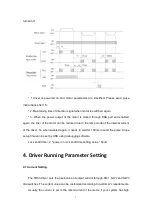
3.3.4 Timing diagram .................................................................................................... 6

4. Driver Running Parameter Setting ................................................................................... 7

4.1 Current Setting ............................................................................................................7

4.2 Automatic Half Flow Settings ..................................................................................... 8

4.3 Subdivision Settings ................................................................................................... 8

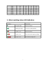
5. Driver working status LED indication ............................................................................... 9

6. Installation .......................................................................................................................10

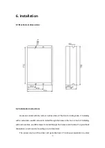
6.1 Mechanical dimensions ............................................................................................ 10

6.2 Installation Instructions ............................................................................................. 10

7. Appendix A. Guarantee Clause ......................................................................................11

Summary of Contents for 5R60

Page 1: ...5R60 USER MANUAL Shenzhen Rtelligent Mechanical Electrical Technology Co Ltd...

Page 2: ...on 5 3 3 1 Pulse Direction Signal 5 3 3 2 Enable Signal 6 3 3 3 error output interface connection 6 3 3 4 Timing diagram 6 4 Driver Running Parameter Setting 7 4 1 Current Setting 7 4 2 Automatic Half...

Page 3: ...has overvoltage undervoltage phase current and total current overcurrent protection Its input and output control signals are optically isolated 2 Characteristic indicators 2 1 Features Power supply 24...

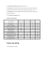
Page 4: ...d as brake control Communication interface USB 2 2 Electrical Specifications Drive parameter Minimum value Typical value Maximum unit Supply voltage 24 48 VDC Output current peak 0 5 3 A Control signa...

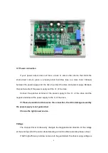
Page 5: ...e positive terminal of the power supply to the V of the drive and the negative terminal of the power supply to the V of the drive Please be careful not to reverse the connection the drive damage cause...

Page 6: ...more the supply voltage exceeds the motor voltage the less supply current is required When the motor is connected to a 48V power supply the power supply output current is half of the 24V power supply...

Page 7: ...y when the EN signal is high optocoupler is on the driver power is partially turned off and the motor is not energized The EN input can be used to restart the drive when the motor is in an error state...

Page 8: ...e internal current of the driver So when enabled again it needs to wait for 100ms to send the pulse Slope setup time can be set by USB using debugging software Lock shaft time 2 power on lock shaft ti...

Page 9: ...will be reduced to 50 of the running current when the switch is set to ON the idle current will be reduced to 100 of the running current After the driver stops receiving the pulse for 2 seconds it en...

Page 10: ...n light The driver is working properly 1 green 1 red Driver overcurrent 1 green 2 red Driver input power supply overvoltage 1 green 3 red Driver internal voltage error 20000 OFF ON ON OFF 25000 ON OFF...

Page 11: ...ling base If installing with a wide side use M3 screws to install through the holes in the four corners If installing with narrow sides use M3 screws to install through the holes on both sides For goo...

Page 12: ...ance service for our products during the warranty period A 2 Exclude the following Improper connection such as the polarity of the power supply is reversed and insert pull the motor connection when th...

Reviews: