6
floating or low, the motor runs clockwise. When the DIR signal is high, the motor runs
counterclockwise.
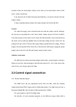
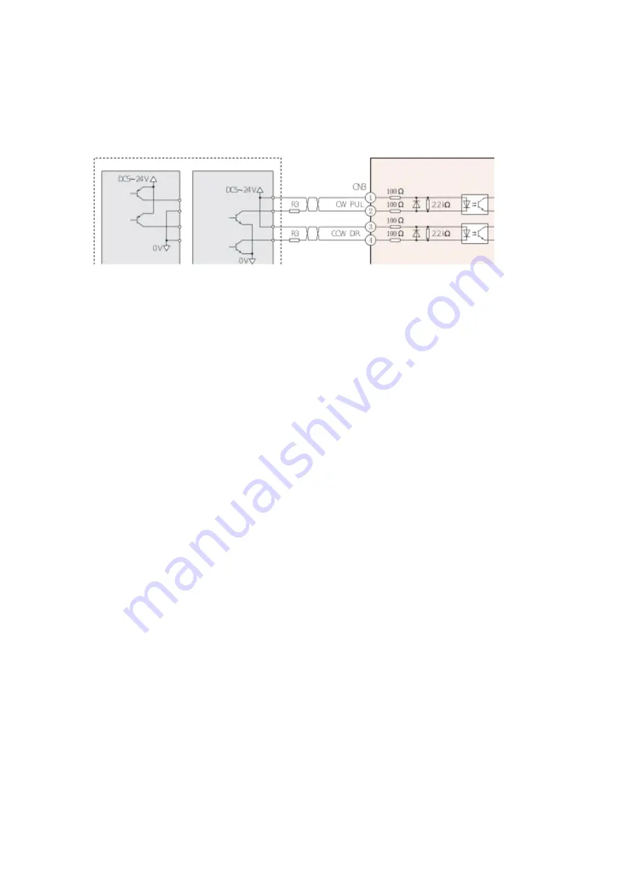
When the pulse input is an open collector, the wiring is as follows:
3.3.2 Enable Signal
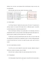
The EN input enables or disables the power section of the driver. The signal input is
optically isolated and accepts 5VDC single-ended or differential signals. An external
current-limiting resistor is required for greater than 5V.
When the EN signal is floating or low (optocoupler is not conducting), the driver is
enabled and the motor is running normally; when the EN signal is high (optocoupler is on),
the driver power is partially turned off and the motor is not energized.
The EN input can be used to restart the drive when the motor is in an error state. First,
the existing fault is eliminated from the application system, and then a falling edge signal
is input to the EN terminal. The driver can restart the power section and the motor is
excited.
3.3.3 error output interface connection
The OUT port is an opto-isolated OC output with a maximum withstand voltage of
30VDC and a maximum saturation current of 100mA.
When the driver is working normally, the output optocoupler does not turn on.
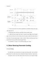
3.3.4 Timing diagram
The following figure shows that the optocoupler is turned ON and the optocoupler is


