


12
3.1.2.1.POWER ON
Pressing this switch causes the furnace to go through its power up
sequence, providing the MAIN lamp is lit and the EPOs (Emergency
Power Off switches) and interlocks located in the doors are released.
The ON indicator, described in 2.1.1.2, will illuminate.
3.1.2.2.POWER OFF
Before pressing POWER OFF, the furnace must be in cooldown mode.
Pressing this switch causes the furnace to begin a timed power shutdown
sequence. The heaters are shut down immediately, and after a cooldown
(to 100
o
C) period, the fans, transport belt, and other functions are shut
down.
3.2.
Basic Operation
3.2.1.
Main Power
The MAIN indicator must be lit before pressing the POWER ON button.
3.2.2.
Uninterruptible Power Supply (UPS) “ON” Switch (Option)
The UPS power “ON” switch is located on the center front panel of the UPS.
3.2.3.
Power On/Startup
Press the POWER ON button. The ON indicator illuminates. Press the monitor
power button. The computer boots up and the logo screen is displayed.
CAUTION: Dangerous voltages are now present throughout the electrical
systems of the furnace. Make sure that any probes in the furnace are placed
on the belt surface only. Probes extending over the sides of the belt may
contact high voltage terminals!
3.2.4.
Fans
Check that the control enclosure fans, the cabinet cooling exhaust fans, and the
turbulent product cooling fans are turning. If the exhaust for the furnace is located
on the bottom of the machine, it is important to have the bottom fan at greater than
or equal to the power of the top fan. If this is not done the cooling system will not
work properly.
3.2.5.
Furnace Log-on and Initial Operation
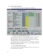
Select “Security” icon to initiate access to “Security and User Information” screen.
Summary of Contents for 2115150301
Page 23: ...22 Figure 3 8 1 1 Event Logging ...
Page 44: ...43 Section 6 PRODUCT SPECIFICATION 6 PRODUCT SPECIFICATION ...
Page 62: ...61 View Product Tracking ...
Page 83: ...82 ...


